


150
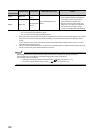
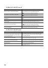
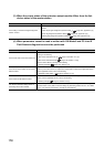
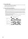
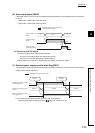
(3) When the output status of the extension output module differs from the link
device status of the master station
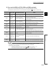
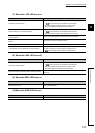
(4) When parameters cannot be read or written with GX Works2 and CC-Link IE
Field Network diagnostics cannot be performed
Check item Action
Is the setting of the external signal assignment
function correct?
Check that the following settings are not used in the external signal assignment
function.
• Alert output signal assignment (address: 0004
H
) ( Page 164, Appendix 3 (3))
• Error flag assignment (address: 0005
H
) ( Page 165, Appendix 3 (4))
• Warning flag assignment (address: 0006
H
) ( Page 166, Appendix 3 (5))
Check item Action
Is the D LINK LED of the main module on?
Check for the D LINK LED of the main module and if it is not on, perform troubleshooting by
referring to the following.
• When the D LINK LED turns off ( Page 146, Section 11.4 (5))
• When the D LINK LED flashes ( Page 146, Section 11.4 (6))
Check for other LEDs by referring to the following.
• Checking the LEDs ( Page 145, Section 11.4)
Is the version of the module on the master
station correct?
Check the serial number (first five digits) of the module on the master station, and if the
version is prior to the correct one, replace the module with a module of the applicable version.
For the applicable version, refer to the following.
• Applicable master station ( Page 44, Section 5.2 (1))
Is the version of GX Works2 correct?
Check the version of GX Works2, and if the version is prior to the applicable one, update GX
Works2. For the applicable version, refer to the following.
• Software package ( Page 44, Section 5.2 (4))
Are network parameter settings same as
the settings of the CPU module?
Perform "Verify with PLC" and check that network parameter settings match the settings of
the CPU module. If they differ, match the settings by performing "Read from PLC" and "Write
to PLC", and write the parameters to modules on slave stations.