


77
CHAPTER 8 FUNCTION
8
8.1 Mode Shift at Power-on
CHAPTER 8 FUNCTION
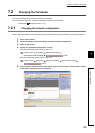
This chapter describes the details of the functions available in the D/A converter module, and the setting procedures
for those functions.
For details on remote I/O signals, remote registers, and remote buffer memory, refer to the following.
• Details of Remote I/O Signals ( Page 151, Appendix 1)
• Details of Remote Register Areas ( Page 158, Appendix 2)
• Details of Remote Buffer Memory Areas ( Page 162, Appendix 3)
8.1 Mode Shift at Power-on
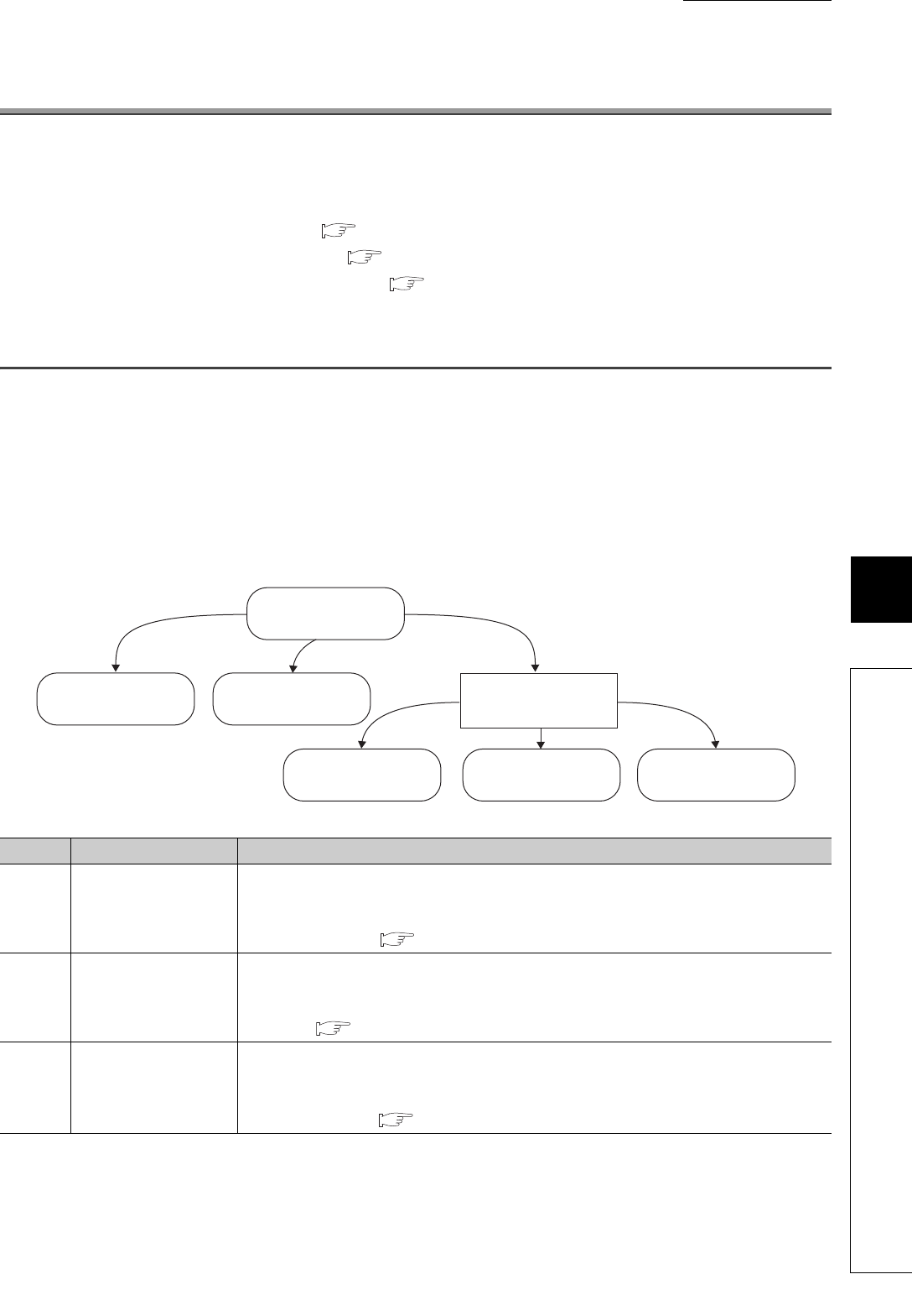
At power-on, the mode of the D/A converter module shifts to any of the following.
• Offset/gain setting mode
• Unit test mode
• Normal mode
• Trigger output mode
• Synchronous communication mode
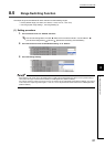
The following table lists conditions where the mode shifts.
Symbol Mode Condition
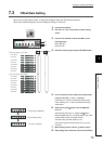
a) Offset/gain setting mode
If "X10" of the station number setting switch is set to "O/G", the mode shifts to the offset/gain
setting mode.
For details, refer to the following.
• Offset/Gain Setting ( Page 75, Section 7.3)
b) Unit test mode
If "X10" of the station number setting switch is set to "TEST" and "X1" of the switch is set to "0", the
mode shifts to the unit test mode.
For details, refer to the following.
• Unit test ( Page 148, Section 11.5)
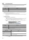
c) (Drive mode switch)
If the station number setting switch is set to 1 to 120, the mode shifts according to the setting of
Mode switch (address: 0000
H
).
For details, refer to the following.
• Drive Mode Switch ( Page 78, Section 8.2)
c)
b)
a)
Unit test modeOffset/gain setting mode
Trigger output mode
Power-on
(Drive mode switch)
Normal mode
Synchronous
communication mode