21
CHAPTER 2 PART NAMES
2
3)
P1
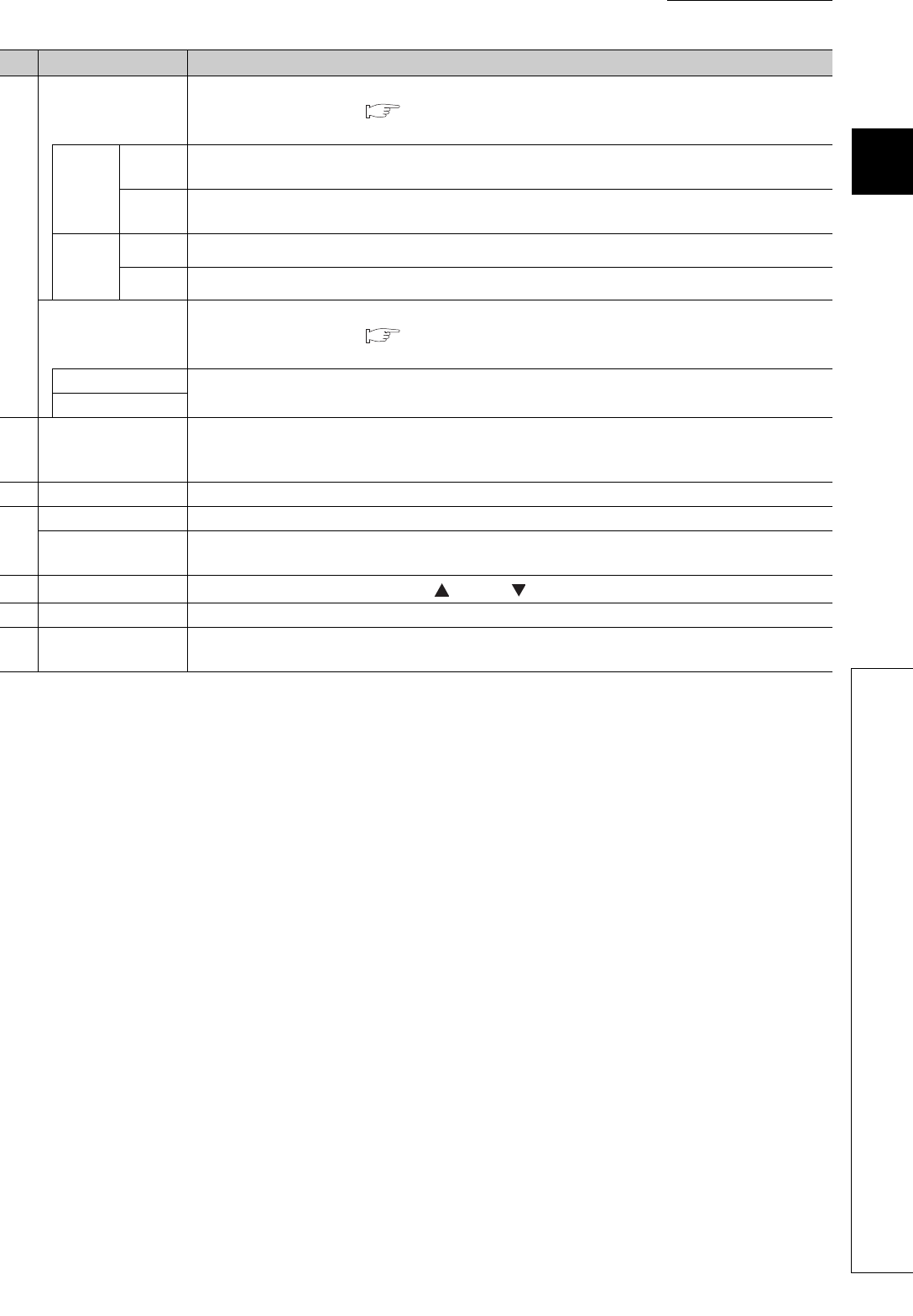
PORT1 connector for CC-Link IE Field Network (RJ45 connector)
Connect an Ethernet cable. ( Page 54, Section 6.5)
There are no restrictions on the connection order of the cables for the "P1" connector and "P2" connector.
L ER
LED
(red)
ON
• The module has received abnormal data.
• The module is performing loopback.
OFF
• The module has received normal data.
• The module is not performing loopback.
LINK
LED
(green)
ON Linkup in progress.
OFF Linkdown in progress.
P2
PORT2 connector for CC-Link IE Field Network (RJ45 connector)
Connect an Ethernet cable. ( Page 54, Section 6.5)
There are no restrictions on the connection order of the cables for the "P1" connector and "P2" connector.
L ER LED (red)
(Same as the "P1" connector)
LINK LED (green)
4)
Terminal block for
module power supply
and FG
A terminal block to connect the module power supply (24VDC) and FG.
5) DIN rail hook A hook to mount a module on a DIN rail.
6)
Terminal block cover Covers for preventing electric shock while the power is on.
Terminal block for
analog output signals
A 2-piece screw terminal block for connecting to the external device.
7) SET/SEL button
Select the setting target by pressing the button or button in the offset/gain setting mode.
8) +/- button Select the analog output value by pressing the + button or - button in the offset/gain setting mode.
9)
Extension connector
cover
A cover to protect a connector of an extension module. Do not remove the cover when an extension
module is not connected to the connector.
No. Name Application


