33
CHAPTER 3 SPECIFICATIONS
3
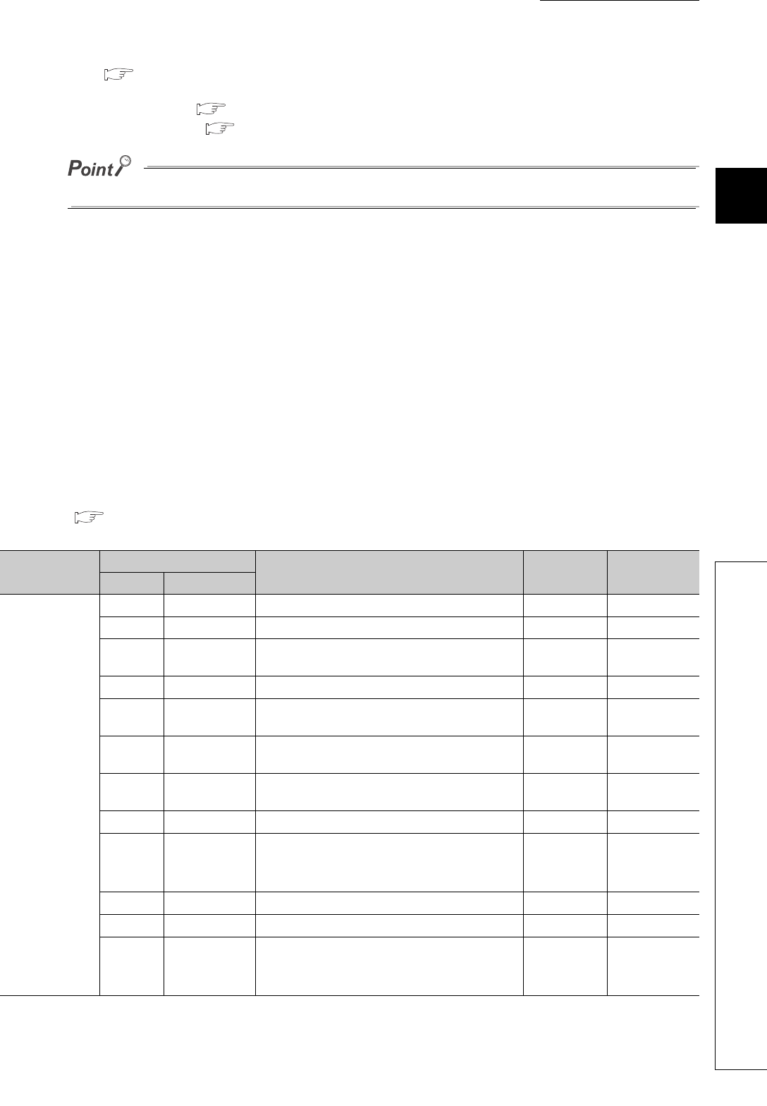
3.7 List of Remote Buffer Memory
*1 For the REMFR and REMTO instructions, refer to the following.
User's manual for the master/local module used
*2 For the access method, refer to the following.
• Parameter area ( Page 63, Section 7.1)
• Error history area ( Page 135, Section 11.1
)
Do not access the system area using the REMFR or REMTO instruction. Doing so may lead the module to malfunction.
(1) Parameter area (address: 0000
H
to 04FF
H
)
For the parameter area, parameters can be set using the CC IE Field configuration of GX Works2 or using the
REMTO instruction.
The parameter in the parameter area is backed up to the nonvolatile memory.
The parameter backed up to the nonvolatile memory is read to the parameter area when the module power
supply is turned off and on or the module returns from remote reset.
If the parameter is written from the parameter setting of the CC IE Field configuration of GX Works2, it is also
written to the nonvolatile memory at that time. When the parameter is written using the REMTO instruction, it is
written to the nonvolatile memory when Initial data setting request flag (RY9) is turned off and on. At this time, the
parameter is written to the nonvolatile memory even though it is incorrect. When the power supply is turned off
and on with an incorrect parameter written, the incorrect parameter is read from the nonvolatile memory and an
error code is stored to Latest error code (RWr0). Take corrective action according to the error code list.
( Page 138, Section 11.2)
Type
Address
Description
Default
*1
Read/Write
*2
Decimal Hexadecimal
Station-based
parameter data
0
0000
H
Mode switch
0009
H
R/W
1
0001
H
System area - -
2
0002
H
Trigger output signal assignment (for external
signal assignment function)
FFFF
H
FFFF
H
3
0003
H
System area - -
4
0004
H
Alert output signal assignment (for external signal
assignment function)
FFFF
H
R/W
5
0005
H
Error flag assignment (for external signal
assignment function)
FFFF
H
R/W
6
0006
H
Warning flag assignment (for external signal
assignment function)
FFFF
H
R/W
7
0007
H
Cyclic data update watch time setting
0000
H
R/W
8 to 15
0008
H
to
000F
H
System area - -
16
0010
H
Input response time setting
0005
H
R/W
17
0011
H
Digital output HOLD/CLEAR setting
0000
H
R/W
18 to 255
0012
H
to
00FF
H
System area - -


