


2
4
I
7
8
191
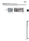
Installation environment. . . . . . . . . . . . . . . . . . . . . 46
Installation environment and installation position . . .46
Installation position . . . . . . . . . . . . . . . . . . . . . . . . 46
L
L ER LED. . . . . . . . . . . . . . . . . . . . . . . . . . . . . . . 21
Latest error code (RWr0) . . . . . . . . . . . . . . . . . . . 158
Latest warning code (RWr1). . . . . . . . . . . . . . . . . 158
Laying Ethernet cables . . . . . . . . . . . . . . . . . . . . . 56
LINK LED. . . . . . . . . . . . . . . . . . . . . . . . . . . . . . . 21
List of remote buffer memory . . . . . . . . . . . . . . . . . 32
List of remote I/O signals . . . . . . . . . . . . . . . . . . . . 29
List of remote register . . . . . . . . . . . . . . . . . . . . . . 31
M
Maintenance and inspection. . . . . . . . . . . . . . . . . 133
Maximum station-to-station distance (Maximum Ethernet
cable length). . . . . . . . . . . . . . . . . . . . . . . . . . . . . 56
Measures to comply with the EMC Directive. . . . . . 180
Cables . . . . . . . . . . . . . . . . . . . . . . . . . . . . . . 183
EMC Directive related standards . . . . . . . . . . . . 180
External power supply . . . . . . . . . . . . . . . . . . . 183
Installation in a control panel . . . . . . . . . . . . . . .182
Others . . . . . . . . . . . . . . . . . . . . . . . . . . . . . . 184
MODE LED . . . . . . . . . . . . . . . . . . . . . . . . . . . . . 20
Mode switch (address: 0000
H
) . . . . . . . . . . . . . . . 162
Module control data area (address: 1000
H
to 14FF
H
)
. . . . . . . . . . . . . . . . . . . . . . . . . . . . . . . . . . . . . . 39
Module operation information initialization command
(address: 1004
H
). . . . . . . . . . . . . . . . . . . . . . . . . 175
Module operation information initialization completed
(address: 1005
H
). . . . . . . . . . . . . . . . . . . . . . . . . 175
Monitoring area (address: 0500
H
to 09FF
H
) . . . . . . .36
Mounting the modules on a DIN rail . . . . . . . . . . . . 49
N
Number of ON times integration function . . . . . . . . 117
O
O/G LED . . . . . . . . . . . . . . . . . . . . . . . . . . . . . . . 20
OFFSET LED . . . . . . . . . . . . . . . . . . . . . . . . . . . . 20
Offset value . . . . . . . . . . . . . . . . . . . . . . . . . . . . 176
Offset/Gain setting . . . . . . . . . . . . . . . . . . . . . . . . 75
P
P1 . . . . . . . . . . . . . . . . . . . . . . . . . . . . . . . . . . . . 21
P2 . . . . . . . . . . . . . . . . . . . . . . . . . . . . . . . . . . . . 21
Packing list. . . . . . . . . . . . . . . . . . . . . . . . . . . . . . 14
Parameter area (address: 0000
H
to 04FF
H
) . . . . . . .33
Parameter area initialization command (address: 1002
H
)
. . . . . . . . . . . . . . . . . . . . . . . . . . . . . . . . . . . . .173
Parameter area initialization completed (address: 1003
H
)
. . . . . . . . . . . . . . . . . . . . . . . . . . . . . . . . . . . . .174
Parameter setting . . . . . . . . . . . . . . . . . . . . . . . . .63
Part names. . . . . . . . . . . . . . . . . . . . . . . . . . . . . . 19
Performance specifications . . . . . . . . . . . . . . . . . . 25
Program example . . . . . . . . . . . . . . . . . . . . . . . .125
Programming . . . . . . . . . . . . . . . . . . . . . . . . . . . 124
Precautions for programming . . . . . . . . . . . . . . 124
Procedure for programming . . . . . . . . . . . . . . . 125
PW LED . . . . . . . . . . . . . . . . . . . . . . . . . . . . . . . 20
R
Range setting (address: 0103
H
) . . . . . . . . . . . . . . 169
Range switching function. . . . . . . . . . . . . . . . . . . . 81
Remote READY (RXB) . . . . . . . . . . . . . . . . . . . . 154
Requirements to compliance with the Low Voltage
Directive . . . . . . . . . . . . . . . . . . . . . . . . . . . . . . 185
RUN LED. . . . . . . . . . . . . . . . . . . . . . . . . . . . . . . 20
S
Scaling enable/disable setting (address: 010E
H
) . . 171
Scaling function . . . . . . . . . . . . . . . . . . . . . . . . . . 85
SET/SEL button . . . . . . . . . . . . . . . . . . . . . . . . . . 21
Shift function . . . . . . . . . . . . . . . . . . . . . . . . . . . . 91
Station number setting . . . . . . . . . . . . . . . . . . . . . 45
Station number setting switch . . . . . . . . . . . . . . . . 19
System configuration. . . . . . . . . . . . . . . . . . . . . . . 43
T
Term . . . . . . . . . . . . . . . . . . . . . . . . . . . . . . . . . . 12
Terminal block cover. . . . . . . . . . . . . . . . . . . . . . . 21
Terminal block for analog output signals . . . . . . . . . 21
Terminal block for module power supply and FG . . . 21
The procedure before operation . . . . . . . . . . . . . . . 41
Trigger output completed clear request (RY1A) . . . 156
Trigger output completed flag (RX19) . . . . . . . . . . 154
Trigger output function . . . . . . . . . . . . . . . . . . . . 101
Trigger output request (RY19) . . . . . . . . . . . . . . . 156
Trigger output signal assignment (address: 0002
H
)
. . . . . . . . . . . . . . . . . . . . . . . . . . . . . . . . . . . . . 163
Troubleshooting . . . . . . . . . . . . . . . . . . . . . . . . . 135
Troubleshooting for each phenomenon . . . . . . . . . 149
U
Unit test. . . . . . . . . . . . . . . . . . . . . . . . . . . . . . . 148
V
V LED . . . . . . . . . . . . . . . . . . . . . . . . . . . . . . . . . 20
Voltage output characteristics . . . . . . . . . . . . . . . 177
W
Warning flag (RX7) . . . . . . . . . . . . . . . . . . . . . . . 151
Warning flag assignment (address: 0006
H
) . . . . . . 166
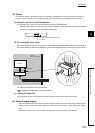
Wiring of Ethernet cable . . . . . . . . . . . . . . . . . . . . 54
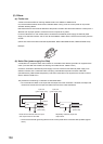
Wiring of external device and terminal block . . . . . . 57
Wiring with terminal block for module power supply and
FG . . . . . . . . . . . . . . . . . . . . . . . . . . . . . . . . . . . 52