


190
INDEX
Symbols
+/- button . . . . . . . . . . . . . . . . . . . . . . . . . . . . . . 21
A
Alarm code list. . . . . . . . . . . . . . . . . . . . . . . . . . 144
Alert output clear request flag (RY1E) . . . . . . . . . 156
Alert output flag (RWrA) . . . . . . . . . . . . . . . . . . . 159
Alert output function . . . . . . . . . . . . . . . . . . . . . . . 98
Alert output setting (address: 105
H
) . . . . . . . . . . . 170
Alert output signal (RX1E). . . . . . . . . . . . . . . . . . 155
Alert output signal assignment (address: 0004
H
) . . 164
ALM LED . . . . . . . . . . . . . . . . . . . . . . . . . . . . . . 20
Analog output HOLD/CLEAR function . . . . . . . . . . 82
Analog output HOLD/CLEAR setting (address: 0104
H
)
. . . . . . . . . . . . . . . . . . . . . . . . . . . . . . . . . . . . 169
Applicable DIN rail model (compliant with IEC 60715)
. . . . . . . . . . . . . . . . . . . . . . . . . . . . . . . . . . . . . 50
Applicable systems . . . . . . . . . . . . . . . . . . . . . . . 44
Applicable master station. . . . . . . . . . . . . . . . . . 44
Connectable modules . . . . . . . . . . . . . . . . . . . . 44
Ethernet cable . . . . . . . . . . . . . . . . . . . . . . . . . 44
Software package . . . . . . . . . . . . . . . . . . . . . . . 44
Application . . . . . . . . . . . . . . . . . . . . . . . . . . . . . 15
B
Bending radius of the Ethernet cable . . . . . . . . . . . 56
C
Calculating current consumption . . . . . . . . . . . . . . 27
CC-Link IE Field Network diagnostic function . . . . 121
CC-Link IE Field Network synchronous communication
function
. . . . . . . . . . . . . . . . . . . . . . . . . . . . . . . 109
CH1 to 4 LED . . . . . . . . . . . . . . . . . . . . . . . . . . . 20
Checking for the error codes and the alarm codes
. . . . . . . . . . . . . . . . . . . . . . . . . . . . . . . . . . . . 135
Checking by executing a command of the slave station
. . . . . . . . . . . . . . . . . . . . . . . . . . . . . . . . . . . 135
Checking by Latest error code (RWr0). . . . . . . . 137
Checking by Latest warning code (RWr1) . . . . . 137
Checking the LEDs . . . . . . . . . . . . . . . . . . . . . . 145
CH Alert output lower limit value (address: 0107
H
,
0109
H
, 010B
H
, 010D
H
) . . . . . . . . . . . . . . . . . . . . 170
CH Alert output upper limit value (address: 0106
H
,
0108
H
, 010A
H
, 010C
H
) . . . . . . . . . . . . . . . . . . . . 170
CH Digital value (RWw2 to RWw5) . . . . . . . . . . 160
CH Output enable/disable flag (RY10 to RY13) . 156
CH Scaling lower limit value (address: 010F
H
, 0111
H
,
0113
H
, 0115
H
) . . . . . . . . . . . . . . . . . . . . . . . . . . 171
CH Scaling upper limit value (address: 0110
H
, 0112
H
,
0114
H
, 0116
H
) . . . . . . . . . . . . . . . . . . . . . . . . . . 171
CH Set value check code (RWr2 to RWr5). . . . . 158
CH Shifting set value (RWw6 to RWw9) . . . . . . 161
Connecting extension modules . . . . . . . . . . . . . . . 48
Connecting the Ethernet cable. . . . . . . . . . . . . . . . 54
Current output characteristics . . . . . . . . . . . . . . . 178
Cyclic data update watch function . . . . . . . . . . . . . 84
Cyclic data update watch time setting (address: 0007
H
)
. . . . . . . . . . . . . . . . . . . . . . . . . . . . . . . . . . . . 167
D
D LINK LED . . . . . . . . . . . . . . . . . . . . . . . . . . . . 20
D/A conversion enable/disable function . . . . . . . . . 80
D/A conversion enable/disable setting (address: 0102
H
)
. . . . . . . . . . . . . . . . . . . . . . . . . . . . . . . . . . . . 168
D/A output enable/disable function . . . . . . . . . . . . 80
Details of remote I/O signals . . . . . . . . . . . . . . . . 151
Digital output HOLD/CLEAR setting (address: 0011
H
)
. . . . . . . . . . . . . . . . . . . . . . . . . . . . . . . . . . . . 168
Digital output HOLD/CLEAR setting function. . . . . 117
Digital value range check function . . . . . . . . . . . . . 95
DIN rail hook . . . . . . . . . . . . . . . . . . . . . . . . . . . . 21
DIN rail stopper . . . . . . . . . . . . . . . . . . . . . . . . . . 51
E
ERR. LED. . . . . . . . . . . . . . . . . . . . . . . . . . . . . . 20
Error clear request flag (RYA) . . . . . . . . . . . . . . . 156
Error code list . . . . . . . . . . . . . . . . . . . . . . . . . . 138
Error flag (RXA). . . . . . . . . . . . . . . . . . . . . . . . . 153
Error flag assignment (address: 0005
H
) . . . . . . . . 165
Error history area (address: 0A00
H
to 0FFF
H
). . . . . 38
Error history clear command (address: 1000
H
) . . . 173
Error history clear completed (address: 1001
H
). . . 173
Error history (address: 0A00
H
to 0AEF
H
) . . . . . 172
Error notification function . . . . . . . . . . . . . . . . . . 114
Extension connector cover . . . . . . . . . . . . . . . . . . 21
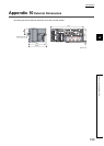
External dimensions. . . . . . . . . . . . . . . . . . . . . . 189
External power supply monitor request flag (RY1F)
. . . . . . . . . . . . . . . . . . . . . . . . . . . . . . . . . . . . 157
External power supply monitor state flag (RX1F). . 155
External power supply monitoring function . . . . . . 117
External signal assignment function. . . . . . . . . . . 118
F
Features. . . . . . . . . . . . . . . . . . . . . . . . . . . . . . . 16
Function at the extension module installation . . . . 117
G
GAIN LED. . . . . . . . . . . . . . . . . . . . . . . . . . . . . . 20
Gain value . . . . . . . . . . . . . . . . . . . . . . . . . . . . 176
General specifications . . . . . . . . . . . . . . . . . . . . . 23
I
I LED . . . . . . . . . . . . . . . . . . . . . . . . . . . . . . . . . 20
Initial data setting completed flag (RX9) . . . . . . . . 152
Initial data setting request flag (RY9) . . . . . . . . . . 156
Input response time setting (address: 0010
H
) . . . . 167
Input response time setting function. . . . . . . . . . . 117
Installation and wiring. . . . . . . . . . . . . . . . . . . . . . 45
Installation direction . . . . . . . . . . . . . . . . . . . . . . . 47