


I
-
I
-
Using Spectrum Analyzer Features
Using limit-line Functions
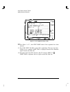
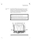
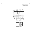
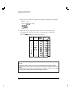
Item Description of Items in Figure 3-6
1
Frequency and amplitude coordinate that starts the first segment.
2
First segment.
3
Frequency and amplitude coordinate that starts the second segment.
4
Second segment.
5
Frequency and amplitude coordinate that starts the third segment.
6
Third segment.
1
Frequency and amplitude coordinate that starts the fourth segment.
8
Fourth segment.
9
Frequency and amplitude coordinate that starts the fifth segment.
IO
Fifth segment.
11
Frequency and amplitude coordinate that starts the sixth segment.
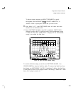
Selecting the Frequency or Press SELECT
FREQ
, then enter a frequency value, or press SELECT TIME
Time Coordinate
and enter a time value, for the segment. Regardless of the table format, a
frequency/time coordinate must be specified.
Limit line coordinates
may
be entered in terms of either frequency and amplitude, or time and
amplitude. Press LIMITS
FRQ
TIME until the desired choice of either frequency or time has
be selected (underlined). If TIME has been selected as the limit line parameter SELECT TIME
will replace SELECT
FREfJ
in the Edit Limit menus.
Selecting the Amplitude
Coordinate
In the previous procedure, pressing SELECT AMPLITUD and then entering an
amplitude value, specified the amplitude coordinate for the upper limit line.
The limit-line table formats dictate how the amplitude values are treated:
l With the upper limit-line table format, one amplitude component
(representing an upper limit-line segment) is specified per
frequency/time component. The amplitude value is entered by pressing
SELECT
AMPLITIJD
, entering an amplitude value, and pressing a units key.
3-44