


I
-
I
-
Making Measurements Using Spectrum Analyzer Mode
Using the Time-Gated Spectrum Analyzer Capability Without the Gate Utility (Option 107 only)
Setting
the
Gate
Delay
and
Gate
Length
Properly,
When
NOT
Using
the
Gate
Utility
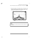
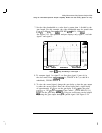
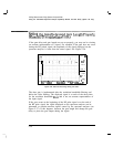
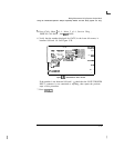
If the gate delay and gate length are not set properly, you may not be viewing
an accurate representation of a signal. For example, If the gate does not occur
during the RF pulsed signal, the amplitude of the signal displayed on the
spectrum analyzer is lower than the actual signal. See Figure 5-26.
“’
)
i...
1
j
.j..
i
I...
.i
j
.;
.._
CLEAR
. .
WRITE
fi
TRACE
fi
B C
-1
.
.
ENTER 50.08 MHz
SPhN
ZB.Bi
Mfiz
tRES
BW 1E0 kHz
#UBW
108
kHz aswp
150
msec
R'
MORE
1
of 3
MAX
HOLO
A
VIEW A
BLANK A
Figure 5-26. Gate Not Occurring During the Pulse
The time gate is implemented after the resolution bandwidth filtering and
before the video filtering. The displayed signal is a result of the decay time
for the resolution bandwidth hlters and is not an accurate representation of
the input signal.
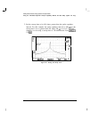
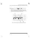
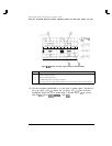
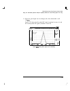
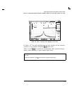
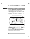
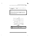
If the gate occurs at the beginning of the RF pulse signal or at the end of
the RF pulse signal, the signal displayed on the spectrum analyzer can be
attenuated or contain transient signals caused by the spectrum analyzer (see
Figure 5-27). If this happens, decrease the gate length and change the gate
delay to place the gate output during the signal.
5-50
-