


I
-
I
-
Making Basic Measurements Using Spectrum Analyzer Mode
Comparing Signals Using Delta Markers
REF
48.8
dBm”
PEAK
LOG
10
dB/
WA
SE
SC
FC
CORR
MARKER
*
STOP
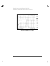
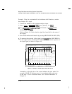
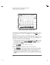
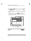
Figure 4-13. Using the Marker to Peak/Peak Function
The frequency and amplitude differences between the signals appear in the
active function block. In addition, the softkeys accessed by
[E)
appear on
the screen.
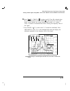
Example: Measure the frequency and amplitude difference between two
signals that do not appear on the screen at one time. (This technique is useful
for harmonic distortion tests when narrow span and narrow bandwidth are
necessary to measure the low-level harmonics.)
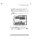
1. Connect the spectrum analyzer’s CAL OUT to the INPUT 75
61
(if you have
not already done so). Press
(jPRESETI),
[FREQUENCY], 300
INIHz),
(SPAN) and
the step down key
((JJ)
to narrow the frequency span until only one
signal appears on the screen.
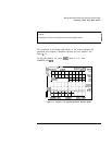
2. Press
CPEAK
SEARCH) to place a marker on the peak.
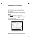
3.
Press MARKER A to identify the position of the first marker.
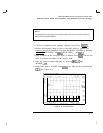
4. Press [FREQUENCY] to activate center frequency. Turn the knob clockwise
slowly to adjust the center frequency until a second signal peak is placed
at the position of the second marker. It may be necessary to pause
occasionally while turning the knob to allow a sweep to update the trace.
The
first
marker remains on the screen at the amplitude of the Erst signal
peak.
4-20