


I
-
Getting Started
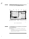
Getting Acquainted with the Analyzer
7
8
9
10
11
12
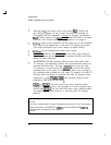
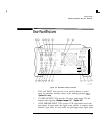
IcoPv]
prints or plots screen data. Use
[CONFIG],
Plot Conf ig or
Print Conf ig , and COPY
DEV
PRMT
PLT before using IcoPv]. See
Chapter 6 for more details.
CONTROL functions access menus that allow you to adjust the
resolution bandwidth, adjust the sweep time, store and manipulate
trace data, and control the instrument display.
MARKER functions control the markers, read out frequencies and
amplitudes along the cable TV-analyzer trace, automatically locate the
signals of highest amplitude, and keep a signal at the marker position
in the center of the screen.
WINDOWS keys, turn on the windows display mode. They allow
switching between windows and control the zone span and location.
DATA keys, STEP keys, and knob allow you to change the numeric
value of an active function.
INPUT 75
D
is the signal input for the cable TV analyzer.
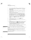
CAUTION
Excessive signal input will damage the cable TV analyzer input attenuator
and input mixer. Use extreme caution when using the cable TV analyzer
around high-power RF sources and transmitters. The maximum input power
that the cable TV analyzer can tolerate appears on the front panel and should
not be exceeded.
Excessive dc voltage can also damage the input attenuator. For your
particular instrument, note the maximum dc voltage that should not be
exceeded on the cable TV analyzer front panel (beneath the INPUT 75
62
connector).
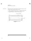
13
14
15
16
17
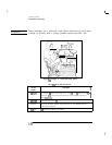
PROBE PWR provides power for high-impedance ac probes or other
accessories.
CAL OUT provides a calibration signal of 300 MHz at 29
dBmV.
VOL-INTEN The VOL-INTEN knob changes the brightness of the
display and the volume of the internal speaker. The inside part of the
knob adjusts the intensity while the outside part adjusts the volume.
TV IN Provides the input for the built-in Television-tuner, Option 107.
Memory card reader reads from or writes to a memory card
2-5