


I
-
I
-
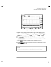
Using Spectrum Analyzer Features
Using Limit-Line Functions
Procedure
for
Creating
an
Upper
and
Lower
Limit
Line
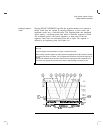
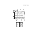
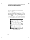
This is a basic procedure for creating a sample of upper and lower limit lines.
The CAL OUT signal is used for the test signal.
1. Press
Lj).
2. Since this procedure uses the calibration signal as the test signal, connect
the cable TV analyzer’s CAL OUT to the INPUT 75
61
with an appropriate
cable.
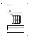
3. Set the cable TV analyzer controls as follows:
FREQUENCY] 300 MHz
&@
50 MHz
m3MHz
4.
Press
c-1
and Limit Lines to access the limit-line menus.
5. At this point you may need to do the following:
a. To save the current limit-line table, press SAVE LIMIT and enter the
register number.
Then press,
Cm].
b.
To clear an existing limit-line table, press Edit Limit ,
Edit; Upper , and More
1
of 2 . Then press PURGE LIMITS two
times.
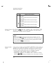
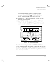
6. (If necessary, press Edit Limit to access the LIMITS
FRq
TIME
softkey.) Press LIMITS
FRCj
TIME so that FRQ is underlined to select
the frequency type of limit line, if it is not already selected.)
7.
Press Edit Up/Low to create upper and lower limit lines simultaneously.
8.
Press More
1
of 2 , LIMITS FIX REL so that FIX is underlined to
select the fixed type of limit line (if it is not already selected.)
3-49