I
-
I
-
Making Measurements Using Spectrum Analyzer Mode
Using the Gate Utility to Simplify Time-Gated Measurements (Option 107 only)
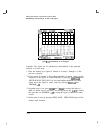
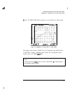
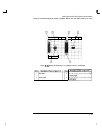
8. The trigger marker reads out the time from the rear panel gate trigger
point to the current marker position. Turn the trigger marker on by
pressing TRIG MKR ON OFF (ON) and use the knob to move the trigger
marker to the edge of the pulse. The marker readout indicates the
position of the edge relative to the rear panel trigger. The trigger marker
may be used to perform “settling time” measurements on the rising or
falling edges of a digital communications signal. (Settling time is the time
from the trigger to 90 percent of the stable pulse on/off value.)
9.
Press Main Menu to exit the define time menu.
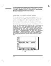
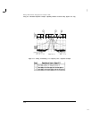
lo. Press Define Gate Use the GATE DELAY and GATE LENGTH keys
to position the gate. Once gate delay or gate length are activated, use
the knob and data entry keys can be used to position the two vertical
gate markers. Select a time interval within the last half of the pulse is
selected.
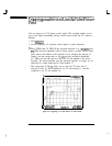
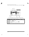
11. Turn the gate on by pressing GATE ON OFF so that ON is underlined.
This activates the frequency domain window, which is the lower window.
The spectrum selected with the current gate position can now be viewed
in the frequency domain window. Press Main Menu .
12. The resolution bandwidth, video bandwidth, and sweep time are not
optimized, so the frequency display may not look correct. There may be
signal dropouts or poor frequency resolution. This can be corrected by
entering the pulse parameters and turning on the coupling.


