


I
-
I
-
FLAT
Flatness
Data
FM COIL
DRIVE
FI4
GAIN
FM
OFFSET
Spectrum Analyzer Mode Key Descriptions
Spectrum Analyzer Mode Functions
draws a zero-slope line between the coordinate point of
the current segment and the coordinate point of the next
segment, producing limit-line values equal in amplitude for
all frequencies between the two points. If the amplitude
values of the two segments differ, the limit line “steps” to
the frequency value of the second segment.
Front-Panel Key Access
(j-1
provides access to the softkeys used for viewing or editing
the flatness-correction constants. This is a service calibration
function and is for service use only.
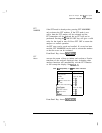
Front-Panel Key Access [CAL)
displays the output of the FM coil driver produced on the
A7
Analog Interface assembly. This is a service diagnostic
function and is for service use only.
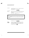
Front-Panel Key Access
ICAL)
adjusts the FM deviation display. The center graticule
represents zero deviation. The top graticule is the positive
deviation set by FM GAIN. The bottom graticule is the
negative deviation set by FM GAIN. The range for FM gain is
from 10
kHz
to 500
kHz.
The default value is 100
kHz.
Front-Panel Key Access
tAUXCTRL_)
or (CAL)
adjusts the horizontal trace for center-screen with no
modulation on the carrier. This is a service diagnostic
function and is for service use only.
Front-Panel Key Access
ICAL)
6-73