


I
-
Making Basic Measurements Using Spectrum Analyzer Mode
Measuring low-level Signals Using Attenuation, Video Bandwidth, and Video Averaging
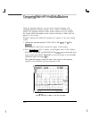
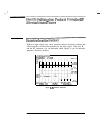
Example: The video-filter control is useful for noise measurements and
observation of low-level signals close to the noise floor. The video filter is
a post-detection low-pass filter that smooths the displayed trace. When
signal responses near the noise level of the spectrum analyzer are visually
masked by the noise, the video filter can be narrowed to smooth this noise
and improve the visibility of the signal. (Reducing video bandwidths requires
slower sweep times to keep the spectrum analyzer calibrated.)
Using the video bandwidth function, measure the amplitude of a low-level
signal.
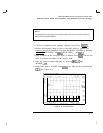
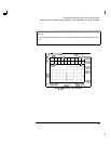
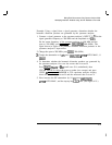
1. As in the first example, connect an antenna to the spectrum analyzer
input. Set the spectrum analyzer to view a low-level signal.
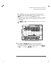
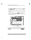
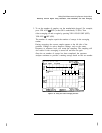
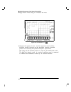
2. Narrow the video bandwidth by pressing
m,
VID BW AUTO MAN , and
the step-down key
((7J-J).
This clarifies the signal by smoothing the noise,
which allows better measurement of the signal amplitude.
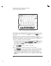
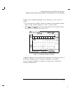
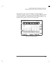
A
“#”
mark appears next to the VBW annotation at the bottom of the
screen, indicating that the video bandwidth is not coupled to the
resolution bandwidth.
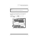
Instrument preset conditions couple the video bandwidth to the resolution
bandwidth so that the video bandwidth is equal to or narrower than
the resolution bandwidth. If the bandwidths are uncoupled when video
bandwidth is the active function, pressing VID BW AUTO MAN (so that
AUTO is underlined) recouples the bandwidths. See Figure 4-18.
4-26