Model 9110TH NOx Analyzer Table of Contents
Teledyne Analytical Instruments 11
TABLE OF CONTENTS
Information About the Specific Configuration of Your Model 9110T NOX Analyzer ..............................................................iii
Mounting Options .............................................................................................................................................................. iv
Pump Mounting Options .................................................................................................................................................... iv
Rear Panel Gas Fittings.................................................................................................................................................... iv
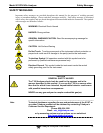
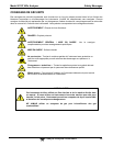
Safety Messages ....................................................................................................................................................................vii
About This Manual ................................................................................................................................................................. ix
PART I GENERAL INFORMATION .................................................................................................................................... 21
1. Introduction, Features and Options ........................................................................................................................................ 23
1.1. Overview ........................................................................................................................................................................ 23
1.2. Features ......................................................................................................................................................................... 23
1.3. Documentation ............................................................................................................................................................... 24
1.4. Options ........................................................................................................................................................................... 24
2. Specifications, Approvals, & Compliance ............................................................................................................................... 27
2.1. Specifications ................................................................................................................................................................. 27
2.2. EPA Equivalency Designation ........................................................................................................................................ 28
2.3. Approvals and Certifications ........................................................................................................................................... 29
2.3.1. Safety ..................................................................................................................................................................... 29
2.3.2. EMC ........................................................................................................................................................................ 29
2.3.3. Other Type Certifications ........................................................................................................................................ 29
3. Getting Started 31
3.1. Unpacking the 9110T Analyzer ...................................................................................................................................... 31
3.1.1. Ventilation Clearance .............................................................................................................................................. 32
3.2. Instrument Layout ........................................................................................................................................................... 32
3.2.1. Front Panel ............................................................................................................................................................. 33
3.2.2. Rear Panel .............................................................................................................................................................. 37
3.2.3. Internal Chassis Layout .......................................................................................................................................... 38
3.3. Connections and Setup .................................................................................................................................................. 41
3.3.1. Electrical Connections ............................................................................................................................................ 41
3.3.2. Pneumatic Connections .......................................................................................................................................... 55
3.4. Startup, Functional Checks, and Initial Calibration ......................................................................................................... 74
3.4.1. Start Up .................................................................................................................................................................. 74
3.4.2. Warning Messages ................................................................................................................................................. 75
3.4.3. Functional Checks .................................................................................................................................................. 77
3.4.4. Initial Calibration ..................................................................................................................................................... 77
3.4.4.1. Interferents .......................................................................................................................................................... 78
PART II – OPERATING INSTRUCTIONS ............................................................................................................................ 85
4. Overview of Operating Modes ................................................................................................................................................ 87
4.1. Sample Mode ................................................................................................................................................................. 88
4.1.1. Test Functions ........................................................................................................................................................ 88
4.1.2. Warning Messages ................................................................................................................................................. 91
4.2. Calibration Mode ............................................................................................................................................................ 92
4.3. Setup Mode .................................................................................................................................................................... 92
4.3.1. Password Security .................................................................................................................................................. 93
4.3.2. Primary Setup Menu ............................................................................................................................................... 93
4.3.3. Secondary Setup Menu (SETUP MORE) ............................................................................................................ 93
5. Setup Menu 95
5.1. SETUP CFG: Configuration Information .................................................................................................................... 95
5.2. SETUP ACAL: Automatic Calibration Option .............................................................................................................. 95
5.3. SETUP DAS: Internal Data Acquisition System .......................................................................................................... 95
5.4. SETUP RNGE: Analog Output Reporting Range Configuration ................................................................................. 96
5.4.1. 9110T Physical Ranges .......................................................................................................................................... 96
5.4.2. 9110T Analog Output Reporting Ranges ................................................................................................................ 96
5.4.3. SETUP RNGE MODE .................................................................................................................................... 98
5.5. SETUP PASS: Password Protection ........................................................................................................................ 106
5.6. SETUP CLK: Setting the Internal Time-of-Day Clock .............................................................................................. 108
5.6.1. Setting the Time of Day ........................................................................................................................................ 108
5.6.2. Adjusting the Internal Clock’s Speed .................................................................................................................... 109
5.7. SETUP COMM: Communications Ports ................................................................................................................... 110
5.7.1. ID (Machine Identification) .................................................................................................................................... 110
5.7.2. INET (Ethernet) .................................................................................................................................................... 111
5.7.3. COM1[COM2] (Mode, Baude Rate and Test Port) ............................................................................................... 111
5.8. SETUP VARS: Variables Setup and Definition ........................................................................................................ 111


