


Model 9110T NOx Analyzer Principles of Operation
Teledyne Analytical Instruments 357
13.7. POWER SUPPLY/CIRCUIT BREAKER
The analyzer operates on 100 VAC, 115 VAC or 230 VAC power at either 50 Hz or 60Hz. Individual
instruments are set up at the factory to accept any combination of these five attributes. A 6.75 amp
circuit breaker is built into the ON/OFF switch. In case of a wiring fault or incorrect supply power, the
circuit breaker will automatically turn off the analyzer.
Under normal operation, the 9110T draws about 1.5 A at 115 V and 2.0 A during start-up.
WARNING
ELECTRICAL SHOCK HAZARD
Should the AC power circuit breaker trip, investigate and correct the condition
causing this situation before turning the analyzer back on.
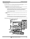
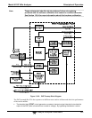
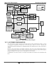
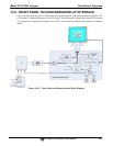
Power enters the analyzer through a standard International Electrotechnical Commission (IEC) 320
power receptacle located on the rear panel of the instrument. From there it is routed through the
ON/OFF Switch located in the lower right corner of the front panel. AC Line power is stepped down
and converted to DC power by two DC power supplies (PS).
One PS provides +5 VDC (3 A) and 15 VDC (1.5/0.5 A) for logic and analog circuitry as well as the
power for the O
3
generator.
A second PS provides +12 VDC (5 A), for the PMT’s thermoelectric cooler, fans and as well as the
various gas stream valves (both standard and optional).
All AC and DC Voltages are distributed via the relay PCA.