


Model 9110T NOx Analyzer Troubleshooting & Service
Teledyne Analytical Instruments 270
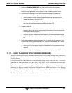
12.3. USING THE INTERNAL ELECTRONIC STATUS LEDS
Several LEDs are located inside the instrument to assist in determining if the analyzer’s CPU, I
2
C bus
and Relay PCA are functioning properly.
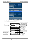
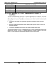
12.3.1. CPU STATUS INDICATOR
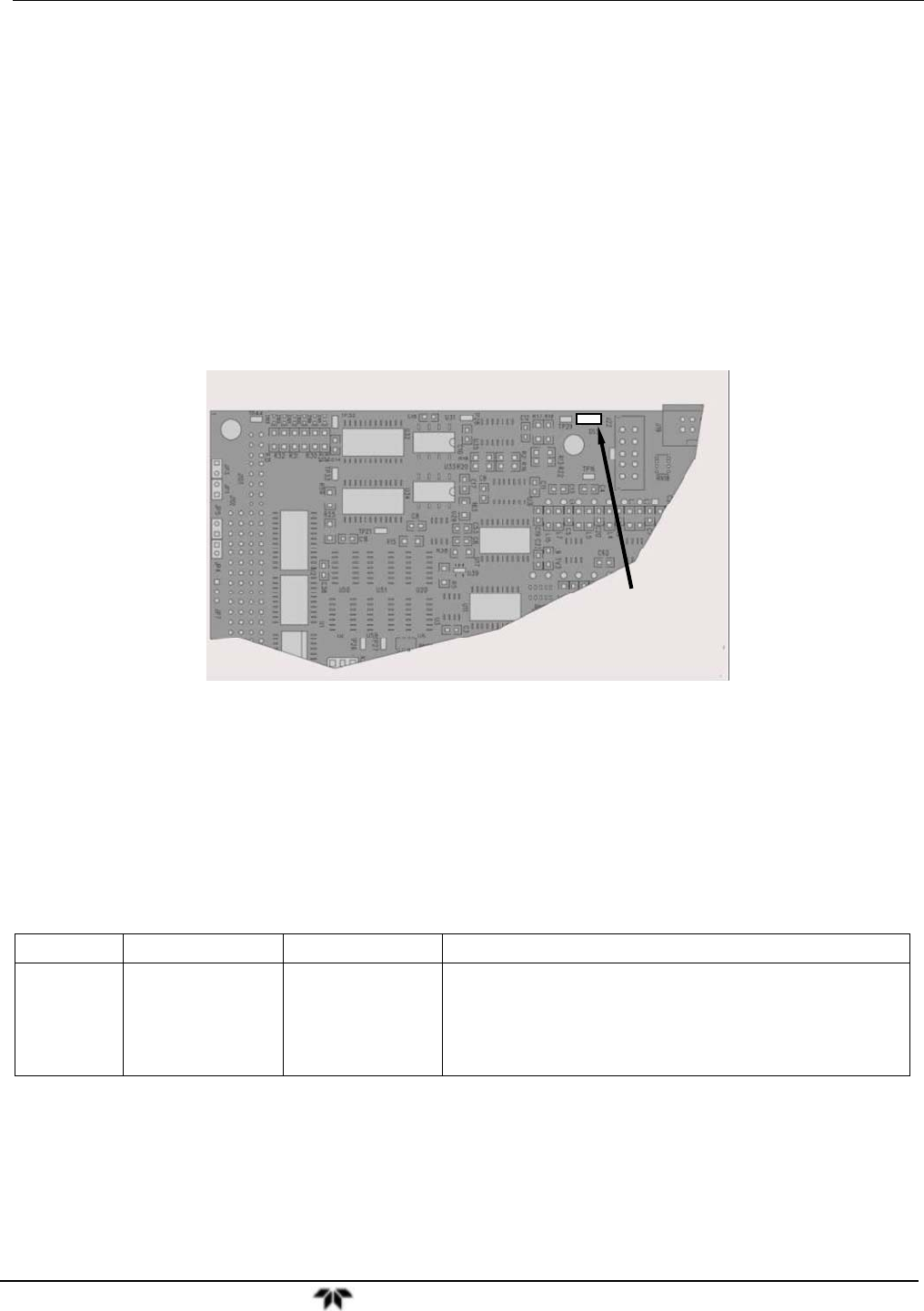
DS5, a red LED, that is located on upper portion of the motherboard, just to the right of the CPU board,
flashes when the CPU is running the main program loop. After power-up, approximately 30 – 60
seconds, DS5 should flash on and off. If characters are written to the front panel display but DS5 does
not flash then the program files have become corrupted, contact TAI's Customer Service Department
(see Section 12.10) because it may be possible to recover operation of the analyzer. If after 30 – 60
seconds, neither DS5 is flashing nor have any characters been written to the front panel display then the
CPU is bad and must be replaced.
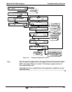
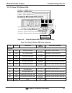
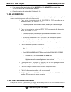
Motherboard
CPU Status LED
Figure 12-2: CPU Status Indicator
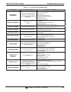
12.3.2. RELAY PCA STATUS LEDS
There are sixteen LEDs located on the Relay PCA. Some are not used on this model.
12.3.2.1. I
2
C Bus Watchdog Status LEDs
The most important is D1, which indicates the health of the I
2
C bus.
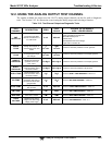
Table 12-4: Relay PCA Watchdog LED Failure Indications
LED Function Fault Status Indicated Failure(s)
D1
(Red)
I
2
C bus Health
(Watchdog Circuit)
Continuously ON
or
Continuously OFF
Failed/Halted CPU
Faulty Motherboard, Touchscreen or Relay PCA
Faulty Connectors/Wiring between Motherboard,
Touchscreen or Relay PCA
Failed/Faulty +5 VDC Power Supply (PS1)
If D1 is blinking, then the other LEDs can be used in conjunction with DIAG Menu Signal I/O to
identify hardware failures of the relays and switches on the Relay PCA.