


Model 9110T NOx Analyzer Getting Started
Teledyne Analytical Instruments 64
Sample Gas pressure must equal ambient atmospheric pressure (no greater than 1.0 psig).
In applications where the sample gas is received from a pressurized manifold, a vent must be
placed on the sample gas line. This vent line must be no more than 10 meters long.
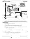
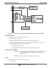
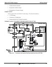
CALIBRATION GAS SOURCES
SPAN GAS Attach a gas line from the source of calibration gas (e.g. a Teledyne
M700E Dynamic Dilution Calibrator) to the SPAN1 inlet (see Figure
3-20). Use PTFE tubing; minimum O.D ¼”.
ZERO AIR Zero air is supplied by the zero air generator such as a Teledyne
M701. Attach a gas line from the source of zero air to the ZERO AIR
inlet.
VENTING
In order to prevent back diffusion and pressure effects, both the span gas and zero air supply lines
should be:
Vented outside the enclosure.
Not less than 2 meters in length.
Not greater than 10 meters in length.
EXHAUST OUTLET
Attach an exhaust line to the EXHAUST OUTLET fitting. The exhaust line should be:
¼” PTFE tubing
maximum 10 meters long
Vented outside the 9110T analyzer’s enclosure
Note Once the appropriate pneumatic connections have been made, check all
pneumatic fittings for leaks using the procedures defined in Section
13.3.12.
To find instructions on calibrating a 9110T with this option installed, see
section 10.4.
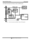
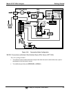
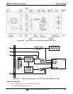
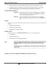
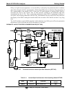
PNEUMATIC LAYOUT FOR AMBIENT ZERO/AMBIENT SPAN VALVES (OPT 50A)