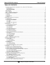
Model 9110T NOx Analyzer Table of Contents
Teledyne Analytical Instruments 14
12.7.2. DC Power Supply ............................................................................................................................................... 283
12.7.3. I
2
C Bus ............................................................................................................................................................... 285
12.7.4. LCD/Display Module ........................................................................................................................................... 285
12.7.5. Relay PCA .......................................................................................................................................................... 285
12.7.6. Motherboard ....................................................................................................................................................... 285
12.7.7. Pressure / Flow Sensor Assembly ...................................................................................................................... 289
12.7.8. CPU .................................................................................................................................................................... 290
12.7.9. RS-232 Communications .................................................................................................................................... 290
12.7.10. NO2 NO Converter ....................................................................................................................................... 291
12.7.11. Simplified GPT Calibration ................................................................................................................................ 296
12.7.12. Photomultiplier Tube (PMT) Sensor Module ..................................................................................................... 300
12.7.13. PMT Preamplifier Board ................................................................................................................................... 302
12.7.14. PMT Temperature Control PCA ........................................................................................................................ 303
12.7.15. O
3
Generator .................................................................................................................................................... 304
12.7.16. Internal Span Gas Generator and Valve Options ............................................................................................. 305
12.7.17. Temperature Sensor ......................................................................................................................................... 306
12.8. Service Procedures .................................................................................................................................................... 308
12.8.1. Disk-On-Module Replacement Procedure .......................................................................................................... 308
12.8.2. O
3
Generator Replacement ................................................................................................................................ 309
12.8.3. Sample and Ozone (Perma Pure
®
) Dryer Replacement ..................................................................................... 309
12.8.4. PMT Sensor Hardware Calibration ..................................................................................................................... 310
12.8.5. Replacing the PMT, HVPS or TEC ..................................................................................................................... 312
12.8.6. Removing / Replacing the Relay PCA from the Instrument ................................................................................ 315
12.9. Frequently Asked Questions ...................................................................................................................................... 316
12.10. Technical Assistance ................................................................................................................................................ 318
13. Principles of Operation ....................................................................................................................................................... 319
13.1. Measurement Principle ............................................................................................................................................... 319
13.1.1. Chemiluminescence Creation in the 9110T Reaction Cell .................................................................................. 319
13.1.2. Chemiluminescence Detection in the 9110T Reaction Cell ................................................................................ 320
13.1.3. NO
X
and NO
2
Determination ............................................................................................................................... 321
13.1.4. Auto Zero ............................................................................................................................................................ 322
13.1.5. Measurement Interferences ................................................................................................................................ 323
13.2. Pneumatic Operation .................................................................................................................................................. 326
13.2.1. Sample Gas Flow ............................................................................................................................................... 326
13.2.2. Flow Rate Control - Critical Flow Orifices ........................................................................................................... 330
13.2.3. Ozone Gas Generation and Air Flow .................................................................................................................. 332
13.2.4. Pneumatic Sensors ............................................................................................................................................. 335
13.3. Electronic Operation ................................................................................................................................................... 338
13.3.1. Overview ............................................................................................................................................................. 338
13.3.2. CPU .................................................................................................................................................................... 339
13.3.3. Motherboard ....................................................................................................................................................... 340
13.3.4. Relay PCA .......................................................................................................................................................... 345
13.4. Sensor Module, Reaction Cell .................................................................................................................................... 351
13.5. Photo Multiplier Tube (PMT) ....................................................................................................................................... 352
13.5.1. PMT Preamplifier ................................................................................................................................................ 353
13.5.2. PMT Cooling System .......................................................................................................................................... 355
13.6. Pneumatic Sensor Board ............................................................................................................................................ 356
13.7. Power Supply/Circuit Breaker ..................................................................................................................................... 357
13.7.1. AC Power Configuration ..................................................................................................................................... 358
13.8. Front Panel Touchscreen/Display Interface ................................................................................................................ 363
13.8.1. LVDS Transmitter Board ..................................................................................................................................... 364
13.8.2. Front Panel Touchscreen/Display Interface PCA ............................................................................................... 364
13.9. Software Operation .................................................................................................................................................... 364
13.9.1. Adaptive Filter ..................................................................................................................................................... 365
13.9.2. Temperature/Pressure Compensation (TPC) ..................................................................................................... 365
13.9.3. Calibration - Slope and Offset ............................................................................................................................. 365
14. A Primer on Electro-Static Discharge ................................................................................................................................. 367
14.1. How Static Charges are Created ................................................................................................................................ 367
14.2. How Electro-Static Charges Cause Damage .............................................................................................................. 368
14.3. Common Myths About ESD Damage ......................................................................................................................... 369
14.4. Basic Principles of Static Control ................................................................................................................................ 369
14.4.1. General Rules ..................................................................................................................................................... 369
14.5. Basic anti-ESD Procedures for Analyzer Repair and Maintenance ............................................................................ 371
14.5.1. Working at the Instrument Rack ......................................................................................................................... 371
14.5.2. Working at an Anti-ESD Work Bench ................................................................................................................. 371


