


Model 9110T NOx Analyzer Troubleshooting & Service
Teledyne Analytical Instruments 262
1. Note any WARNING MESSAGES and take corrective action as necessary.
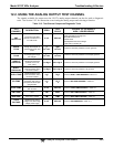
2. Examine the values of all TEST functions and compare them to factory values.
Note any major deviations from the factory values and take corrective action.
3. Use the internal electronic status LEDs to determine whether the electronic
communication channels are operating properly.
Verify that the DC power supplies are operating properly by checking the
voltage test points on the relay PCA.
Note that the analyzer’s DC power wiring is color-coded and these colors match
the color of the corresponding test points on the relay PCA.
4. Suspect a leak first!
Customer service data indicate that the majority of all problems are eventually
traced to leaks in the internal pneumatics of the analyzer or the diluent gas and
source gases delivery systems.
Check for gas flow problems such as clogged or blocked internal/external gas
lines, damaged seals, punctured gas lines, a damaged / malfunctioning pumps,
etc.
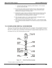
5. Follow the procedures defined in Section 3.4.3 to confirm that the analyzer’s vital
functions are working (power supplies, CPU, relay PCA, touchscreen, PMT cooler,
etc.).
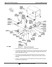
See Figure 3-5 or the general layout of components and sub-assemblies in the
analyzer.
See the wiring interconnect diagram and interconnect list in Appendix D.
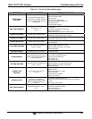
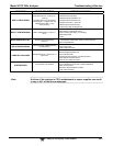
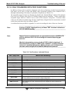
12.1.1. FAULT DIAGNOSIS WITH WARNING MESSAGES
The most common and/or serious instrument failures will result in a warning message being displayed on
the front panel. Table 12-1 lists warning messages, along with their meaning and recommended
corrective action.
It should be noted that if more than two or three warning messages occur at the same time, it is often an
indication that some fundamental sub-system (power supply, relay PCA, motherboard) has failed rather
than an indication of the specific failures referenced by the warnings.
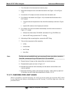
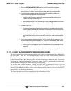
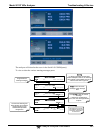
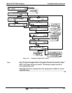
The analyzer will alert the user that a Warning Message is active by flashing the FAULT LED and
displaying the Warning message in the Param field along with the CLR button (press to clear Warning
message). The MSG button displays if there is more than one warning in queue or if you are in the TEST
menu and have not yet cleared the message.
The following display/touch screen examples provide an illustration of each: