


Model 9110T NOx Analyzer Instrument Maintenance
Teledyne Analytical Instruments 260
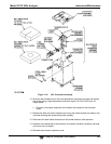
6. If the analyzer is equipped with an IZS Option Connect the leak checker to the Dry
Air inlet and check with soap bubble solution.
7. Once the leak has been located and repaired, the leak-down rate of the indicated
pressure should be less than 1 in-Hg-A (0.4 psi) in 5 minutes after the pressure is
turned off.
8. Clean surfaces from soap solution, reconnect the sample and pump lines and
replace the instrument cover.
9. Restart the analyzer.
11.3.12.3. Performing a Sample Flow Check
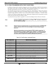
IMPORTANT
IMPACT ON READINGS OR DATA
Use a separate, calibrated flow meter capable of measuring flows between
0 and 1000 cm³/min to measure the gas flow rate though the analyzer. Do
not use the built in flow measurement viewable from the front panel of the
instrument.
This value is only calculated, not measured.
Sample flow checks are useful for monitoring the actual flow of the instrument, as the front panel
display shows only a calculated value. A decreasing, actual sample flow may point to slowly clogging
pneumatic paths, most likely critical flow orifices or sintered filters. To perform a sample flow check:
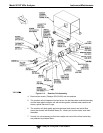
1. Disconnect the sample inlet tubing from the rear panel SAMPLE port.
2. Attach the outlet port of a flow meter to the sample inlet port on the rear panel.
Ensure that the inlet to the flow meter is at atmospheric pressure.
3. The sample flow measured with the external flow meter should be 500 cm³/min ±
10%.
If a combined sample/ozone air Perma Pure dryer is installed (optional
equipment), the flow will be 640 cm³/min ± 10% (500 cm³/min for the sample
and 80 cm³/min for the ozone generator supply air and 60 cm³/min for the purge
flow).
4. Low flows indicate blockage somewhere in the pneumatic pathway.