


Model 9110T NOx Analyzer Principles of Operation
Teledyne Analytical Instruments 356
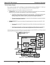
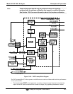
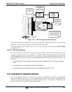
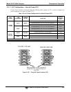
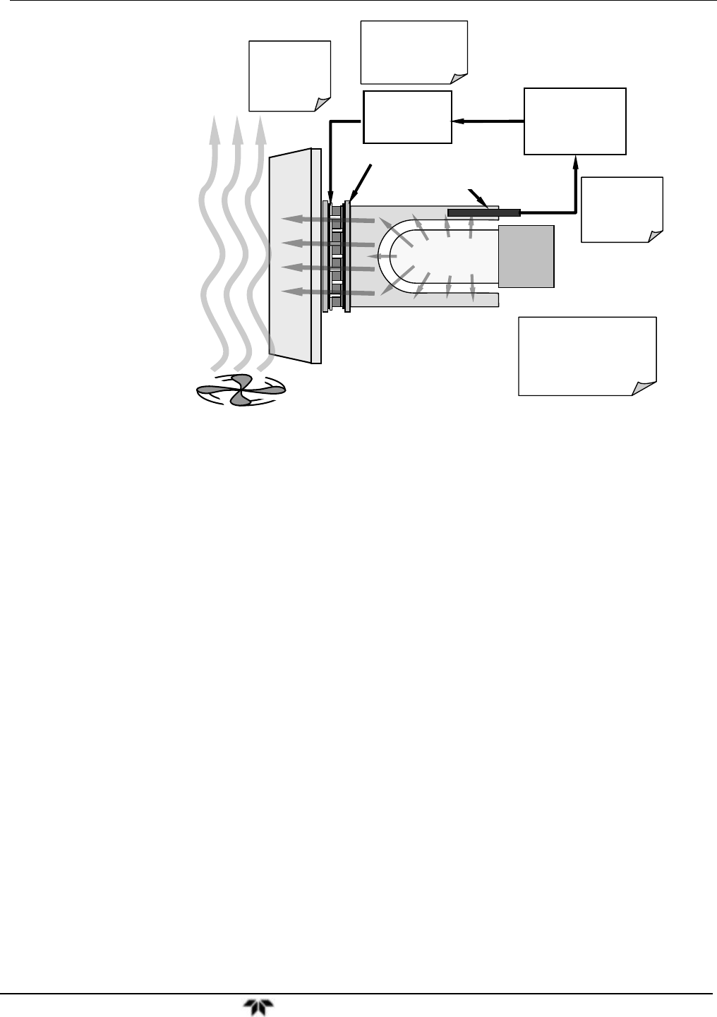
TEC
Control
PCA
PMT
Preamp
PCA
Thermistor
outputs temp of
cold block to
preamp PCA
Preamp PCA sends
buffered and
amplified thermistor
signal to TEC PCA
TEC PCA sets
appropriate
drive voltage for
cooler
Heat form PMT is absorbed
by the cold block and
transferred to the heat sink
via the TEC then bled off
into the cool air stream.
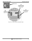
PMT
Cold Block
Heat Sink
Cooling Fan
Thermo-Electric Cooler
PMT Temperature Senso
r
Figure 13-24: PMT Cooling System Block Diagram
The target temperature at which the TEC system keeps the PMT is approximately 8.0ºC. Arriving at this
temperature may take up to 30 minutes after the instrument is turned on.
The actual temperature of the PMT can be viewed via the front panel as the test function PMT TEMP
(see Section 4.1.1).
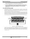
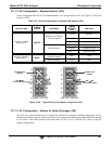
13.5.2.1. TEC Control Board
The TEC control PCA is located on the sensor housing assembly, under the slanted shroud, next to the
cooling fins and directly above the cooling fan. Using the amplified PMT temperature signal from the
PMT preamplifier board (see Section 10.4.5), it sets the drive voltage for the thermoelectric cooler. The
warmer the PMT gets, the more current is passed through the TEC causing it to pump more heat to the
heat sink.
A red LED located on the top edge of this circuit board indicates that the control circuit is receiving
power.
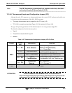
Four test points are also located at the top of this assembly.
For the definitions and acceptable signal levels of these test points see 12.7.14.
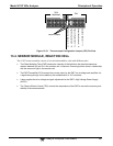
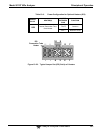
13.6. PNEUMATIC SENSOR BOARD
The flow and pressure sensors of the 9110T are located on a printed circuit assembly just behind the
PMT sensor. Refer to Section 12.7.6.1 for a figure and on how to test this assembly. The signals of this
board are supplied to the motherboard for further signal processing. All sensors are linearized in the
firmware and can be span calibrated from the front panel.