


Model 9110T NOx Analyzer Troubleshooting & Service
Teledyne Analytical Instruments 284
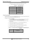
Table 12-6: DC Power Test Point and Wiring Color Codes
NAME TEST POINT# COLOR DEFINITION
DGND
1
Black Digital ground
+5V
2
Red
AGND
3
Green Analog ground
+15V
4
Blue
-15V
5
Yellow
+12R
6
Purple
12 V return
(ground) line
+12V
7
Orange
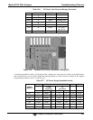
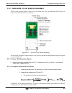
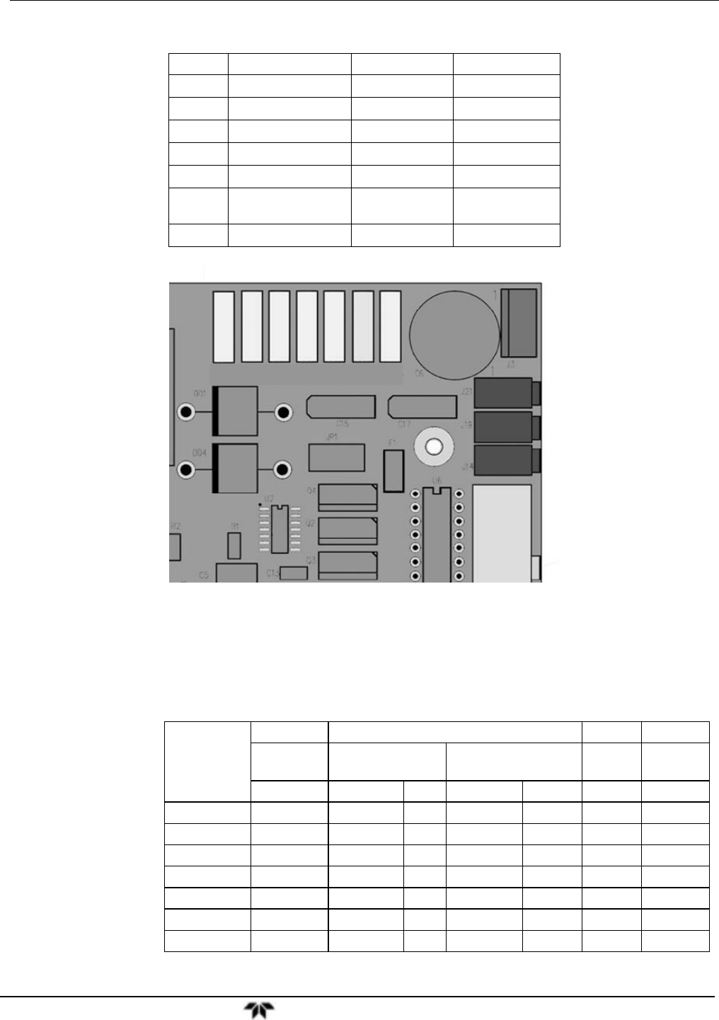
TP1 TP2 TP3 TP4 TP5 TP6 TP7
DGND +5V AGND +15V -15V +12R 12V
Figure 12-4: Location of DC Power Test Points on Relay PCA
A voltmeter should be used to verify that the DC voltages are correct per the values in the table below,
and an oscilloscope, in AC mode, with band limiting turned on, can be used to evaluate if the supplies
are producing excessive noise (> 100 mV p-p).
Table 12-7: DC Power Supply Acceptable Levels
POWER
SUPPLY
VOLTAGE CHECK
RELAY BOARD TEST POINTS MIN V MAX V
FROM
Test Point
TO
Test Point
NAME # NAME #
PS1 +5 DGND 1 +5 2 +4.85 +5.25
PS1 +15 AGND 3 +15 4 +13.5 +16.0
PS1 -15 AGND 3 -15V 5 -13.5 -16.0
PS1 AGND AGND 3 DGND 1 -0.05 +0.05
PS1 Chassis DGND 1 Chassis N/A -0.05 +0.05
PS2 +12 +12V Ret 6 +12V 7 +11.8 +12.5
PS2 DGND +12V Ret 6 DGND 1 -0.05 +0.05