


Model 9110T NOx Analyzer Overview of Operating Modes
Teledyne Analytical Instruments 88
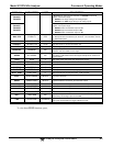
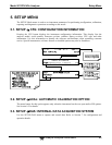
Table 4-1: Analyzer Operating Modes
MODE EXPLANATION
DIAG
One of the analyzer’s diagnostic modes is active.
LO CAL A Unit is performing LOW SPAN (midpoint) calibration initiated automatically by the analyzer’s
AUTOCAL feature
LO CAL R Unit is performing LOW SPAN (midpoint) calibration initiated remotely through the COM ports or
digital control inputs.
M-P CAL
This is the basic calibration mode of the instrument and is activated by pressing the CAL button.
SAMPLE
Sampling normally, flashing text indicates adaptive filter is on.
SAMPLE A
Indicates that unit is in SAMPLE mode and AUTOCAL feature is activated.
SETUP X.#
2
SETUP mode is being used to configure the analyzer. The gas measurement will continue during
setup.
SPAN CAL A
1
Unit is performing SPAN calibration initiated automatically by the analyzer’s AUTOCAL feature
SPAN CAL M
1
Unit is performing SPAN calibration initiated manually by the user.
SPAN CAL R
1
Unit is performing SPAN calibration initiated remotely through the COM ports or digital control
inputs.
ZERO CAL A
1
Unit is performing ZERO calibration procedure initiated automatically by the AUTOCAL feature
ZERO CAL M
1
Unit is performing ZERO calibration procedure initiated manually by the user.
ZERO CAL R
1
Unit is performing ZERO calibration procedure initiated remotely through the COM ports or digital
control inputs.
1
Only Appears on units with Z/S valve or IZS options.
2
The revision of the analyzer firmware is displayed following the word SETUP, e.g., SETUP G.3.
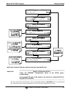
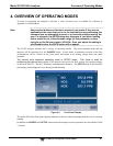
4.1. SAMPLE MODE
This is the analyzer’s standard operating mode. In this mode, the instrument is a calculating
NO
x
, NO and NO
2
concentrations. These values are displayed in the CONC field of the analyzer's front
panel display. While the instrument is in SAMPLE mode, this field provides a readout of all the gas
concentrations being measured by the 9110T: NO
x
, NO and NO
2
.
When the analyzer is in sample mode the PARAM field will display warning messages and test
functions that give the user information about the operational status of the analyzer.
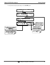
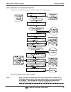
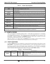
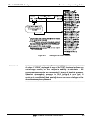
4.1.1. TEST FUNCTIONS
A variety of TEST functions are available for viewing at the front panel whenever the analyzer is at the
MAIN MENU. These functions provide information about the various functional parameters related to
the analyzer’s operation and its measurement of gas concentrations. This information is particularly
when troubleshooting a performance problem with the 9110T (see Section 13). Figure 4-2 will display
the Test Functions on the front panel screen. Table 4-2 lists the available TEST functions.
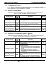
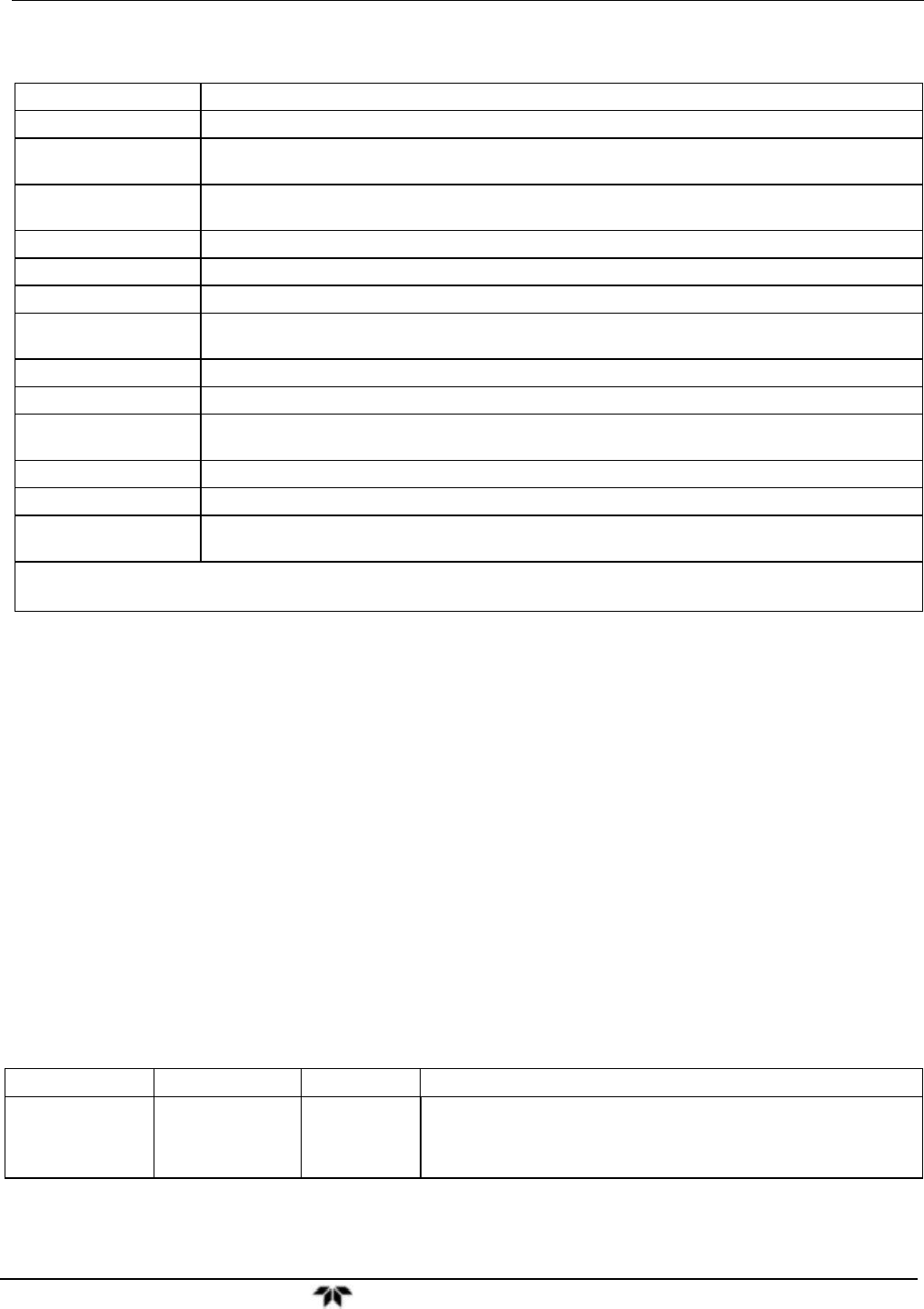
Table 4-2: Test Functions Defined
DISPLAY PARAMETER UNITS DESCRIPTION
RANGE
RANGE
PPB,
PPM,
UGM
&
The Full Scale limit at which the reporting range of the analyzer’s ANALOG
OUTPUTS is currently set.
THIS IS NOT the Physical Range of the instrument. See Section
5.4.1 for
more information.