


Model 9110TH NOx Analyzer Getting Started
Teledyne Analytical Instruments 43
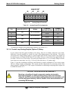
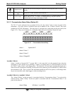
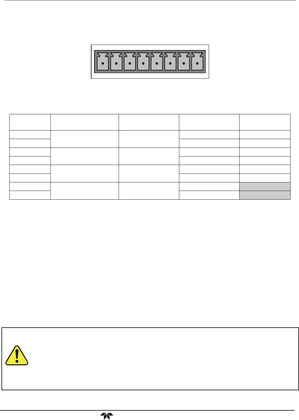
ANALOG OUT
A1 A2 A3 A4
+ - + - + - + -
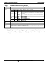
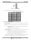
Figure 3-8: Analog Output Connector
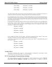
Table 3-5: Analog Output Pin Assignments
PIN ANALOG OUTPUT SIGNAL
STANDARD
VOLTAGE OUTPUT
CURRENT
LOOP OPTION
1
A1
NO
x
Concentration
V Out I Out +
2 Ground I Out -
3
A2
NO Concentration
V Out I Out +
4 Ground I Out -
3
A3
NO
2
Concentration
V Out I Out +
4 Ground I Out -
7
A4
1
TEST CHANNEL
V Out Not Available
8 Ground Not Available
To change the settings for the analog output channels, see Section 5.9.2.
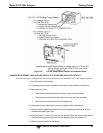
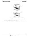
3.3.1.4. Current Loop Analog Outputs (Option 41) Setup
If your analyzer had this option installed at the factory, there are no further connectons to be made.
Otherwise, it can be installed as a retrofit for each of the analog outputs of the analyzer . This option
converts the DC voltage analog output to a current signal with 0-20 mA output current. The outputs can
be scaled to any set of limits within that 0-20 mA range. However, most current loop applications call
for either 2-20 mA or 4-20 mA range. All current loop outputs have a +5% over-range. Ranges with the
lower limit set to more than 1 mA (e.g., 2-20 or 4-20 mA) also have a -5% under-range.
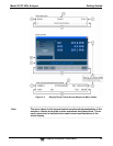
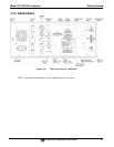
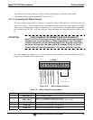
Figure 3-9 provides installation instructions and illustrates a sample combination of one current output
and two voltage outputs configuration. This section provides instructions for converting current loop
analog outputs to standard 0-to-5 VDC outputs. Information on calibrating or adjusting these outputs can
be found in Section 5.9.3.7.
CAUTION – AVOID INVALIDATING WARRANTY
Servicing or handling of circuit components requires electrostatic
discharge protection, i.e. ESD grounding straps, mats and containers.
Failure to use ESD protection when working with electronic assemblies will
void the instrument warranty. Refer to Section 14 for more information on
preventing ESD damage.