


Model 9110T NOx Analyzer Troubleshooting & Service
Teledyne Analytical Instruments 285
12.7.3. I
2
C BUS
Operation of the I
2
C bus can be verified by observing the behavior of D1 on the relay PCA & D2 on the
Valve Driver PCA. Assuming that the DC power supplies are operating properly, the I
2
C bus is operating
properly if D1 on the relay PCA and D2 of the Valve Driver PCA are flashing
There is a problem with the I
2
C bus if both D1 on the relay PCA and D2 of the Valve Driver PCA are
ON/OFF constantly.
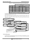
12.7.4. LCD/DISPLAY MODULE
TOUCHSCREEN INTERFACE
Assuming that there are no wiring problems and that the DC power supplies are operating properly, the
display screen should light and show the splash screen and other indications of its state as the CPU goes
through its initialization process.
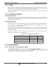
12.7.5. RELAY PCA
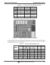
The Relay PCA can be most easily checked by observing the condition of the status LEDs on the Relay
PCA (see Section 12.3.2), and using the SIGNAL I/O submenu under the DIAG menu (see Section
12.1.3) to toggle each LED ON or OFF.
If D1 on the Relay PCA is flashing and the status indicator for the output in question (Heater power,
Valve Drive, etc.) toggles properly using the Signal I/O function, then the associated control device on
the Relay PCA is bad.
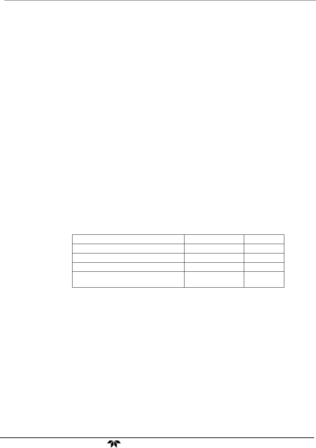
Several of the control devices are in sockets and can be easily replaced. The following table lists the
control device associated with a particular function:
Table 12-8: Relay PCA Control Devices
FUNCTION CONTROL DEVICE SOCKETED
All valves U5 Yes
Reaction Cell Heater K1 Yes
NO
2
NO Converter heater K2 Yes
Permeation Tube Heater for
Optional Internal Span Gas Generator
K4 Yes
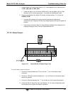
12.7.6. MOTHERBOARD
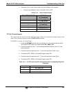
12.7.6.1. Test Channel / Analog Outputs Voltage
The ANALOG OUTPUT submenu, located under the SETUP MORE DIAG menu is used to
verify that the 9110T analyzer’s three analog outputs are working properly. The test generates a signal
on all three outputs simultaneously as shown in the following table: