Model 9110T NOx Analyzer Troubleshooting & Service
Teledyne Analytical Instruments 271
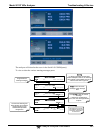
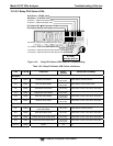
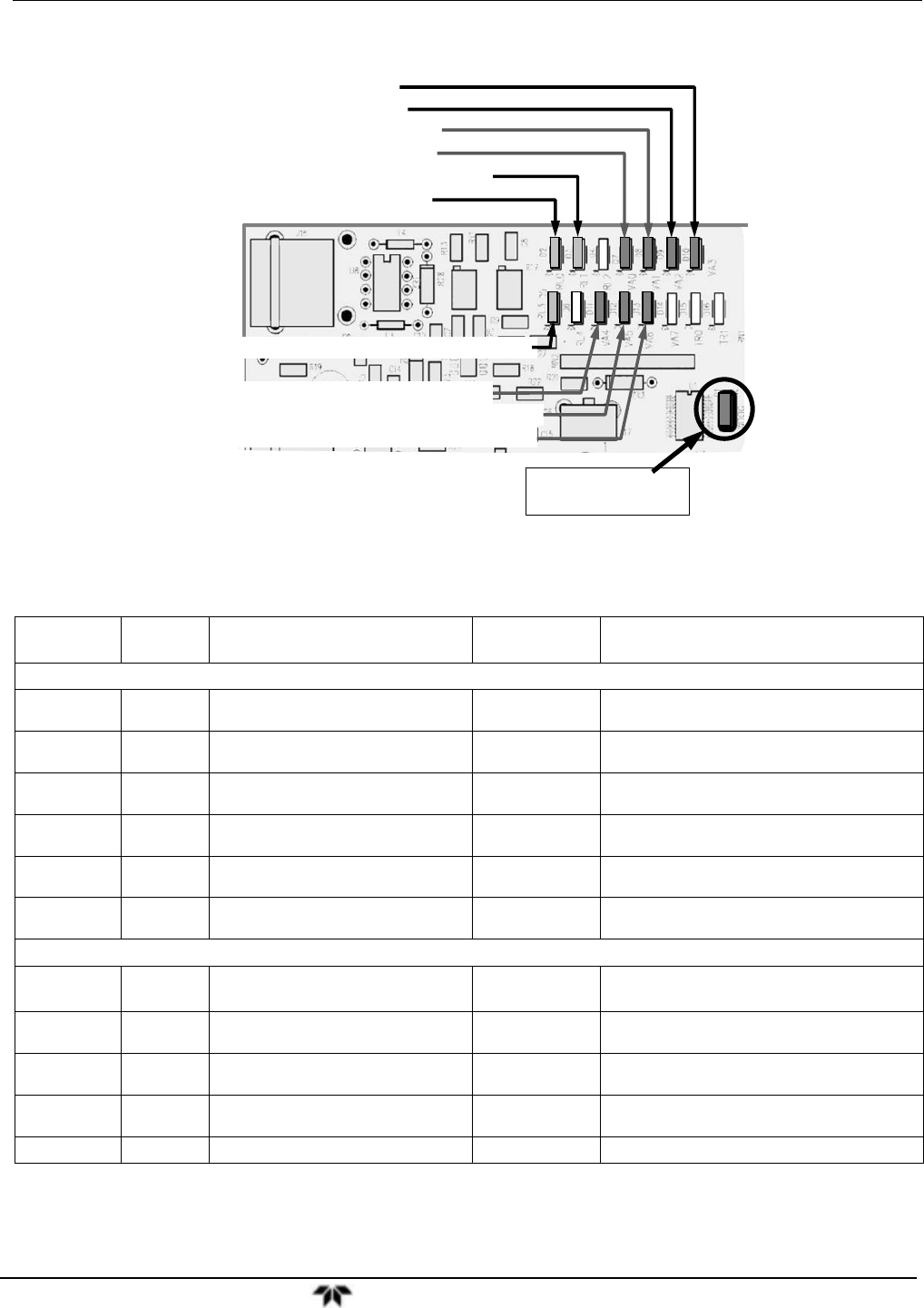
12.3.2.2. Relay PCA Status LEDs
D7 (Green) – Optional Zero/Span Valve
D11 (Green) – Optional Dual Span Select Valve
D12 (Green) – Optional Pressurized Span Shutoff Valve
D3
(
Yellow
)
NO
2
NO Converter Heater
D5 (Yellow) – Optional Internal Span Gas Gen Heater
D8 (Green) – Optional Sample/Cal Valve
D1 (RED)
Watchdog Indicator
D2
(
Yellow
)
Reaction Cell Heater
D9
(
Green
)
–
AutoZero Valve
D10
(
Green
)
–
NO/NO
x
V
alve
D13 (Green) – Optional Pressurized Zero Shutoff Valve
Figure 12-3: Relay PCA Status LEDS Used for Troubleshooting
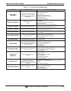
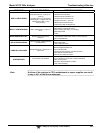
Table 12-5: Relay PCA Status LED Failure Indications
LED COLOR FUNCTION
FAULT
STATUS
INDICATED FAILURE(S)
LED ROW 1
D2
Yellow Reaction Cell heater
Continuously
ON or OFF
Heater broken, thermistor broken
D3 Yellow NO
2
converter heater
Continuously
ON or OFF
Heater broken, thermocouple broken
D7 Green Zero/Span valve status
Continuously
ON or OFF
Valve broken or stuck, valve driver chip broken
D8 Green Sample/Cal valve status
Continuously
ON or OFF
Valve broken or stuck, valve driver chip broken
D9
Green Auto-zero valve status
Continuously
ON or OFF
Valve broken or stuck, valve driver chip broken
D10 Green NO/NO
x
valve status
Continuously
ON or OFF
Valve broken or stuck, valve driver chip broken
LED ROW 2
D5 Yellow
Internal span gas generator
perm tube heater
Continuously
ON or OFF
Heater broken, thermistor broken
D11 Green Dual span select valve
Continuously
ON or OFF
Valve broken or stuck, valve driver chip broken
D12 Green Pressurized Span shutoff valve
Continuously
ON or OFF
Valve broken or stuck, valve driver chip broken
D13 Green Pressurized Zero shutoff valve
Continuously
ON or OFF
Valve broken or stuck, valve driver chip broken
D14- 16 Green Spare
N/A N/A


