


Model 9110T NOx Analyzer Troubleshooting & Service
Teledyne Analytical Instruments 309
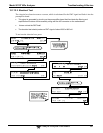
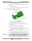
5. Remove the nylon standoff clip that mounts the DOM over the CPU board, and lift
the DOM off the CPU. Do not bend the connector pins.
6. Install the new Disk-on-Module, making sure the notch at the end of the chip
matches the notch in the socket.
7. It may be necessary to straighten the pins somewhat to fit them into the socket.
Press the chip all the way in.
8. Close the rear panel and turn on power to the machine.
9. If the replacement DOM carries a firmware revision, re-enter all of the setup
information.
12.8.2. O
3
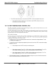
GENERATOR REPLACEMENT
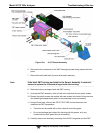
The ozone generator is a black, brick-shaped device with printed circuit board attached to its rear and
two tubes extending out the right side in the front of the analyzer (see Figure 3-5). The board has a red
LED that, when lit, indicates ozone is being generated. To replace the ozone generator:
1. Turn off the analyzer power, remove the power cord and the analyzer cover.
2. Disconnect the 1/8” black tube from the ozone cleanser and the ¼” clear tube from
the plastic extension tube at the brass fitting nearest to the ozone generator.
3. Unplug the electrical connection on the rear side of the brick.
4. Unscrew the two mounting screws that attach the ozone generator to the chassis
and take out the entire assembly.
5. If you received a complete replacement generator with circuit board and mounting
bracket attached, simply reverse the above steps to replace the current generator.
Note Ensure to carry out a leak check (11.3.12) and a recalibration after the
analyzer has warmed up for about 60 minutes.
12.8.3. SAMPLE AND OZONE (PERMA PURE
®
) DRYER REPLACEMENT
The 9110T standard configuration is equipped with a dryer for the ozone supply air. An optional dryer is
available for the sample stream and a combined dryer for both gas streams can also be purchased. To
change one or both of these dryers:
1. Turn off power to the analyzer and pump, remove the power cord and the analyzer
cover.
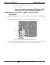
2. Locate the dryers in the center of the instrument, between sensor and NO
2
converter (see Figure 3-5).
They are mounted to a bracket, which can be taken out when unscrewing the
two mounting screws (if necessary).
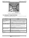
3. Disconnect all tubing that extends out of the dryer assembly.
Take extra care not to twist any of the white plastic fittings on the dryer.