


Model 9110T NOx Analyzer Principles of Operation
Teledyne Analytical Instruments 336
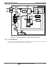
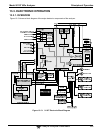
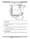
The 9110T uses three pneumatic sensors to verify the flow and pressure levels of its gas streams. They
are located on a printed circuit assembly, called the pneumatic pressure/flow sensor board, located just
behind the sensor assembly. The measurements made by these sensors are used for a variety of
important calculations and diagnostics.
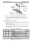
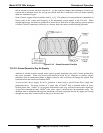
13.2.4.1. Sample Pressure Sensor
An absolute pressure transducer connected to the input of the NO/NO
X
valve is used to measure the
pressure of the sample gas before it enters the analyzer’s reaction cell.
In conjunction with the measurement made by the vacuum pressure sensor, this “upstream”
measurement is used to compute the sample gas sample flow rate and to validate the critical flow
condition (2:1 pressure ratio) through the sample gas critical flow orifice (Section 13.2.2).
If the Temperature/Pressure Compensation (TPC) feature is turned on (Section 13.9.2), the output
of this sensor is also used to supply pressure data for that calculation.
The actual pressure value is viewable through the analyzer’s front panel display as the test function
SAMP.
The flow rate of the sample gas is displayed as SAMP FLW and the SIGNAL I/O function
SAMPLE_PRESSURE.
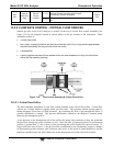
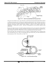
13.2.4.2. Vacuum Pressure Sensor
An absolute pressure transducer connected to the exhaust manifold is used to measure the pressure
downstream from and inside the instrument’s reaction cell.
The output of the sensor is used by the CPU to calculate the pressure differential between the gas
upstream of the reaction cell and the gas downstream from it and is also used as the main
diagnostic for proper pump operation.
If the ratio between the upstream pressure and the downstream pressure falls below 2:1, a warning
message (SAMPLE FLOW WARN) is displayed on the analyzer’s front panel (see Section 4.1.2)
and the sample flow rate will display XXXX instead of an actual value.
If this pressure exceeds 10 in-Hg-A, an RCEL PRESS WARN is issued, even though the analyzer
will continue to calculate a sample flow up to ~14 in Hg.
If the Temperature/Pressure Compensation (TPC) feature is turned on (see Section 13.9.2), the
output of this sensor is also used to supply pressure data for that calculation.
This measurement is viewable through the analyzer’s front panel as the test function RCEL and the
SIGNAL I/O function RCELL_PRESSURE.
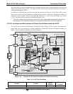
13.2.4.3. Sample Gas Flow Calculation
Sample gas flow in the 9110T analyzer is not a directly measured value, but is rather calculated based on
the measured pressure differential across the sample gas critical flow orifice. Specifically, the upstream
reading of the sample pressure sensor is compared to the downstream pressure reading of the vacuum
pressure sensor and this differential is used, by the analyzer’s CPU, to derive the gas flow rate through
the reaction cell.
The results of this calculation are viewable from the instruments front panel via the test function
SAMP FLW.