


Model 9110T NOx Analyzer Instrument Maintenance
Teledyne Analytical Instruments 256
If tests show that cleaning is necessary, refer to Section 11.3.10 on how to
clean the critical flow orifice.
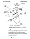
8. Do not remove the sample and ozone nozzles. They are Teflon threaded and
require a special tool for reassembly. If necessary, the manifold with nozzles
attached can be cleaned in an ultrasonic bath.
9. Reassemble in proper order and re-attach the reaction cell to the sensor housing.
Reconnect pneumatics and heater connections, then re-attach the pneumatic
sensor assembly and the cleaning procedure is complete.
10. After cleaning the reaction cell, it is also recommended to exchange the ozone
supply air filter chemical as described in Section 11.3.3.
11. After cleaning, the analyzer span response may drop 10 - 15% in the first 10 days
as the reaction cell window conditions. This is normal and does not require another
cleaning.
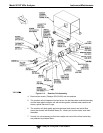
11.3.10. REPLACING CRITICAL FLOW ORIFICES
There are several critical flow orifices installed in the 9110T (see Figure 13-9 for a pneumatic location of
each orifice). Despite the fact that these flow restrictors are protected by sintered stainless steel filters,
they can, on occasion, clog up, particularly if the instrument is operated without sample filter or in an
environment with very fine, sub-micron particle-size dust.
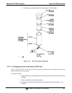
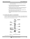
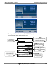
Figure 11-7: Critical Flow Orifice Assembly
To clean or replace a critical flow orifice: