


Model 9110T NOx Analyzer Principles of Operation
Teledyne Analytical Instruments 347
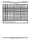
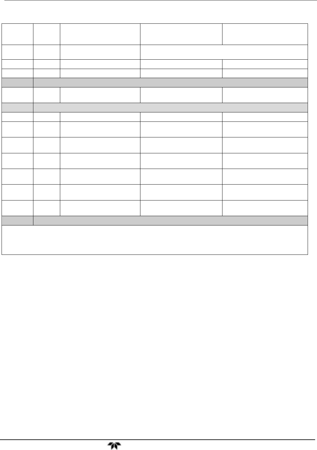
Table 13-4: Relay PCA Status LED’s
LED Color Function
Status When Lit
(Energized State)
Status When Unlit
(Default State)
D1
Red Watchdog Circuit
Cycles ON/OFF every 3 Seconds
under direct control of the analyzer’s CPU.
D2 Yellow Reaction Cell Heater Heating Not Heating
D3 Yellow NO
2
NO Converter Heater Heating Not Heating
D4 SPARE
D5
1
Yellow
Internal Span Gas Generator
Perm Tube Oven Heater
Heating Not Heating
D6
SPARE
D7 Green Zero/Span Valve
Valve OPEN to span gas flow Valve OPEN to zero gas flow
D8 Green Sample/Cal Valve
Valve OPEN to
calibration gas flow
Valve OPEN to
sample gas flow
D9 Green Auto Zero Valve
Sample gas flow BYPASSES
the reaction cell
Sample gas flow is routed
THROUGH the reaction cell
D10 Green NO/NO
x
Valve
Gas flow routed THROUGH
NO
2
NO converter
Gas Flow BYPASSES
NO
2
NO converter
D11
2
Green
Dual Span Gas
Select Valve
Valve OPEN to SPAN 1
gas inlet
Valve OPEN to SPAN2 inlet
D12
3
Green
Pressurized Span
Shutoff Valve
Span gas flow SHUTOFF Span gas flow OPEN
D13
4
Green
Pressurized Zero
Shutoff Valve
Zero gas flow SHUTOFF Zero gas flow OPEN
D14 - 16 SPARE
1
Only active when the optional internal span gas generator is installed.
2
Only active when the dual pressurized span option is installed.
3
Only active when one of the pressurized span gas options is installed.
4
Only active when one the pressurized zero gas option is installed.