


Model 9110T NOx Analyzer Troubleshooting & Service
Teledyne Analytical Instruments 291
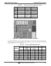
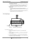
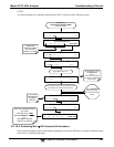
Incorrect cabling and connectors. See Section 3.3.1.8, Figure 3-13 for connector and pin-out
information.
The BAUD rate and protocol are incorrectly configured. See Section 6.2.2.
If a modem is being used, additional configuration and wiring rules must be observed. See Section
8.3
Incorrect setting of the DTE – DCE Switch. See Section 6.1 to set correctly.
Verify that cable (P/N 03596) that connects the serial COMM ports of the CPU to J12 of the
motherboard is properly seated.
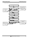
12.7.9.2. Troubleshooting Analyzer/Modem or Terminal Operation
These are the general steps for troubleshooting problems with a modem connected to a Teledyne
analyzer.
1. Check cables for proper connection to the modem, terminal or computer.
2. Check to ensure that the DTE-DCE is in the correct position as described in
Section 6.1.
3. Check to ensure that the set up command is correct (see Section 8.3).
4. Verify that the Ready to Send (RTS) signal is at logic high. The 9110T sets
pin 7 (RTS) to greater than 3 volts to enable modem transmission.
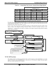
5. Ensure that the BAUD rate, word length, and stop bit settings between
modem and analyzer match. See Section 6.2.2.
6. Use the RS-232 test function to send “w” characters to the modem, terminal
or computer. See Section 6.2.3.
7. Get your terminal, modem or computer to transmit data to the analyzer
(holding down the space bar is one way); the green LED should flicker as the
instrument is receiving data.
8. Ensure that the communications software or terminal emulation software is
functioning properly.
Note Further help with serial communications is available in a separate manual
“RS-232 Programming Notes” TAI P/N 01350.
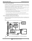
12.7.10. NO2 NO CONVERTER
Provided that oxygen was present in the Sample stream during operation for the NO
2
converter to
function properly, the NO
2
converter assembly can fail in two ways:
An electrical failure of the band heater and/or the thermocouple control circuit and;