


Model 9110T NOx Analyzer Getting Started
Teledyne Analytical Instruments 38
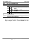
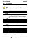
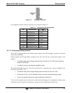
Table 3-3: Rear Panel Description
Component Function
cooling fan
Pulls ambient air into chassis through side vents and exhausts through rear.
AC power
connector
Connector for three-prong cord to apply AC power to the analyzer.
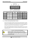
CAUTION! The cord’s power specifications (specs) MUST comply with the power
specs on the analyzer’s rear panel Model number label
Model/specs label
Identifies the analyzer model number and provides power specs
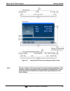
TO CONV
(not used)
FROM CONV
(not used)
MULTI
(not used)
TO DRYER
(not used)
FROM DRYER
Outlet for internal sample gas dryer; connect to external zero air scrubber (for IZS options
only).
SAMPLE
Connect a gas line from the source of sample gas here.
Calibration gases can also enter here on units without zero/span/shutoff valve options
installed.
EXHAUST
Connect an exhaust gas line of not more than 10 meters long here that leads outside the
shelter or immediate area surrounding the instrument. The line must be ¼” tubing or
greater.
SPAN 1
On units with zero/span/shutoff valves option installed, connect a gas line to the source of
calibrated span gas here.
SPAN2/VENT
On units with pressurized span valve option, used for venting.
ZERO AIR
Internal Zero Air: On units with zero/span/shutoff valves option installed but no internal
zero air scrubber attach a gas line to the source of zero air here.
RX TX
LEDs indicate receive (RX) and transmit (TX) activity on the when blinking.
COM 2
Serial communications port for RS-232 or RS-485.
RS-232
Serial communications port for RS-232 only.
DCE DTE
Switch to select either data terminal equipment or data communication equipment during
RS-232 communication.
STATUS
For ouputs to devices such as Programmable Logic Controllers (PLCs).
ANALOG OUT
For voltage or current loop outputs to a strip chart recorder and/or a data logger.
CONTROL IN
For remotely activating the zero and span calibration modes.
ALARM
Option for concentration alarms and system warnings.
ETHERNET
Connector for network or Internet remote communication, using Ethernet cable
ANALOG IN
Option for external voltage signals from other instrumentation and for logging these
signals
USB
Connector for direct connection to laptop computer, using USB cable.
Model Label
Includes voltage and frequency specifications
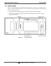
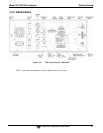
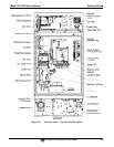
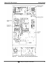
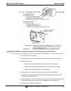
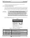
3.2.3. INTERNAL CHASSIS LAYOUT
Figure 3-5 and Figure 3-6 show internal chassis configurations with different options.