


Model 9110T NOx Analyzer Getting Started
Teledyne Analytical Instruments 32
With no power to the unit, carefully removed the top cover of the analyzer and check for internal
shipping damage by carrying out the following steps:
1. Carefully remove the top cover of the analyzer and check for internal shipping
damage.
2. Remove the setscrew located in the top, center of the Front panel.
3. Slide the cover backwards until it clears the analyzer’s front bezel.
4. Lift the cover straight up.
5. Inspect the interior of the instrument to ensure all circuit boards and other
components are in good shape and properly seated.
6. Check the connectors of the various internal wiring harnesses and pneumatic hoses
to ensure they are firmly and properly seated.
7. Verify that all of the optional hardware ordered with the unit has been installed.
These are listed on the paperwork accompanying the analyzer.
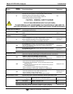
WARNING – ELECTRICAL SHOCK HAZARD
Never disconnect PCAs, wiring harnesses or electronic subassemblies
while under power.
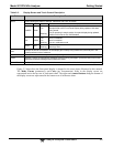
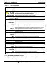
3.1.1. VENTILATION CLEARANCE
Whether the analyzer is set up on a bench or installed into an instrument rack, be sure to leave sufficient
ventilation clearance.
Table 3-1: Ventilation Clearance
AREA
MINIMUM REQUIRED
CLEARANCE
Back of the instrument
10 cm / 4 in
Sides of the instrument
2.5 cm / 1 in
Above and below the instrument
2.5 cm / 1 in
Various rack mount kits are available for this analyzer. Refer to Section 1.4 of this manual for more
information.
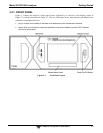
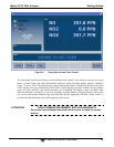
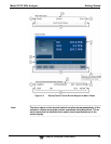
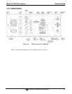
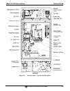
3.2. INSTRUMENT LAYOUT
Instrument layout shows front panel and display, rear panel connectors, and internal chassis layout.