


Model 9110T NOx Analyzer Principles of Operation
Teledyne Analytical Instruments 329
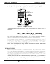
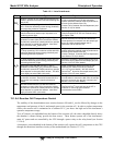
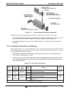
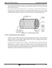
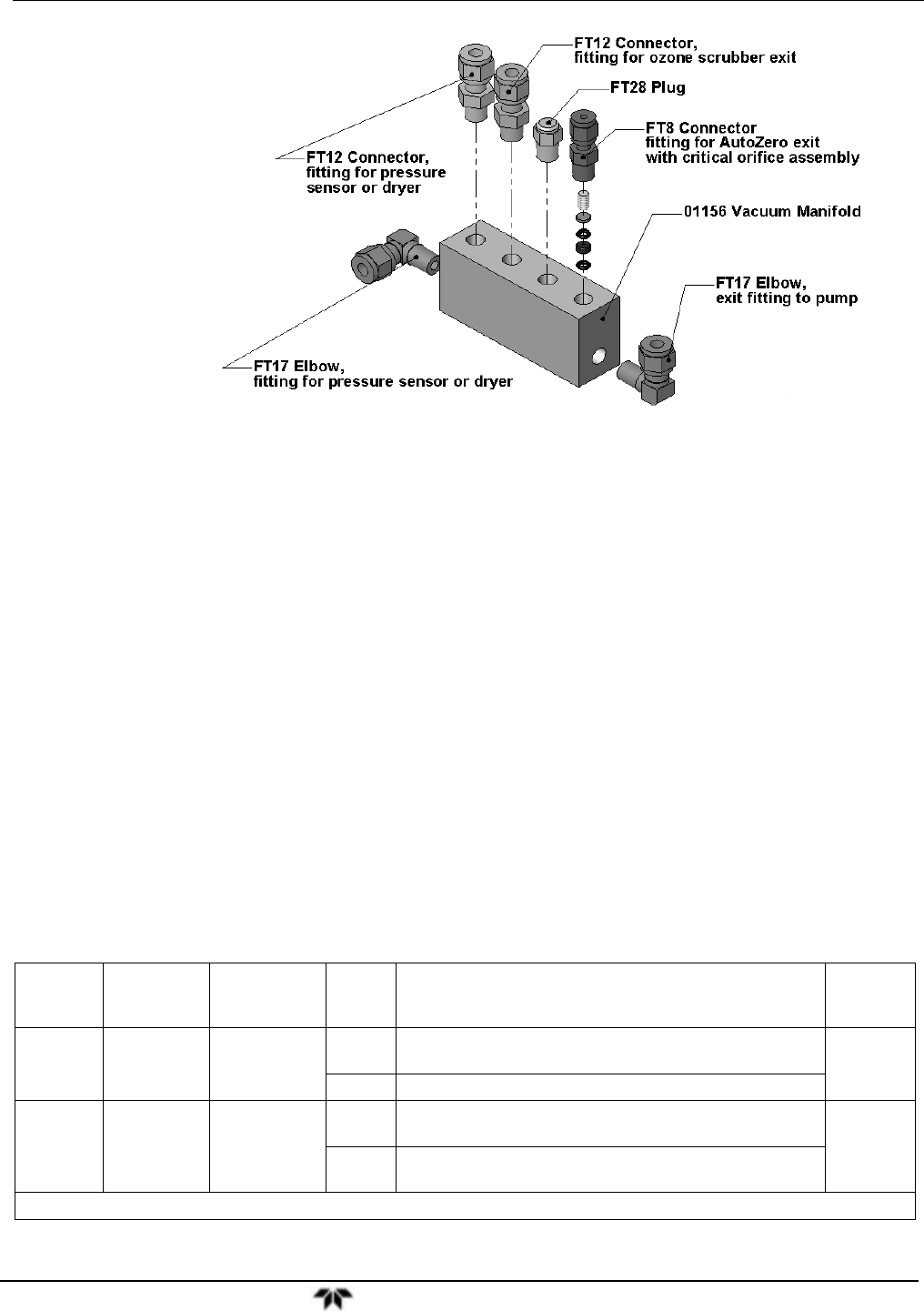
Figure 13-7. Vacuum Manifold, Standard Configuration
Configurations will vary depending on the optional equipment that is installed. For example:
An 9110T with the optional internal span gas generator installed will add another FT8 connector and
orifice assembly to the manifold where the FT28 fitting is shown in the above drawing.
An optional sample gas dryer will add a Tee-fitting so that two ¼” tubes can be connected to the
same port.
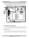
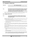
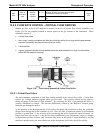
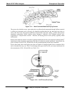
13.2.1.2. Sample Gas Flow Valves and Routing
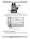
As discussed in Section 13.1, the measurement of NO
x
, NO and NO
2
requires that the sample gas flow
cycles through different routes that include and exclude various scrubbers and converters. There are
several valves that perform this function:
The NO/NO
X
valve directs the sample gas either directly to the reaction cell or through the unit’s
NO
2
converter, alternating every ~8 sec.
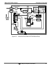
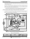
The Auto Zero valve directs the sample gas stream to completely bypass the reaction cell for dark
noise measurement once every minute, which is then subtracted as a measurement offset from the
raw concentration signal.
Table 13-2: 9110T Valve Cycle Phases
Phase
NO/ NO
X
Valve
Status
Auto Zero
Valve
Status
Time
Index
Activity Figure
NO
Measure
Open to
Auto Zero
valve
Open to
reaction cell
0 - 2 s
Wait period (NO dwell time). Ensures reaction cell has
been flushed of previous gas.
Figure
13-3
2 - 4 s Analyzer measures chemiluminescence in reaction cell.
NO
X
Measure
Open to
NO
2
converter
Open to
reaction cell
4 – 6 s
Wait period (NO
X
dwell time). Ensures reaction cell has
been flushed of previous gas.
Figure
13-3
6 – 8 s
Analyzer measures NO + O
3
chemiluminescence in
reaction cell.
Cycle repeats every ~8 seconds