


Model 9110T NOx Analyzer Troubleshooting & Service
Teledyne Analytical Instruments 287
1. Use the Signal I/O function (see Section 12.1.3 and Appendix A) to view the value
of REF_4096_MV and REF_GND.
If both are within 3 mV of nominal (4096 and 0), and are stable, ±0.2 mV then
the basic A/D is functioning properly. If not then the motherboard is bad.
2. Choose a parameter in the Signal I/O function list (see Section 12.1.3) such as
OZONE_FLOW .
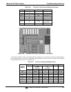
Compare this voltages at its origin (see the interconnect drawing and
interconnect list in Appendix D) with the voltage displayed through the signal I/O
function.
If the wiring is intact but there is a large difference between the measured and
displayed voltage (±10 mV) then the motherboard is bad.
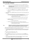
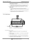
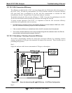
12.7.6.3. Status Outputs
V
+DC Gnd
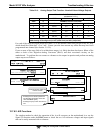
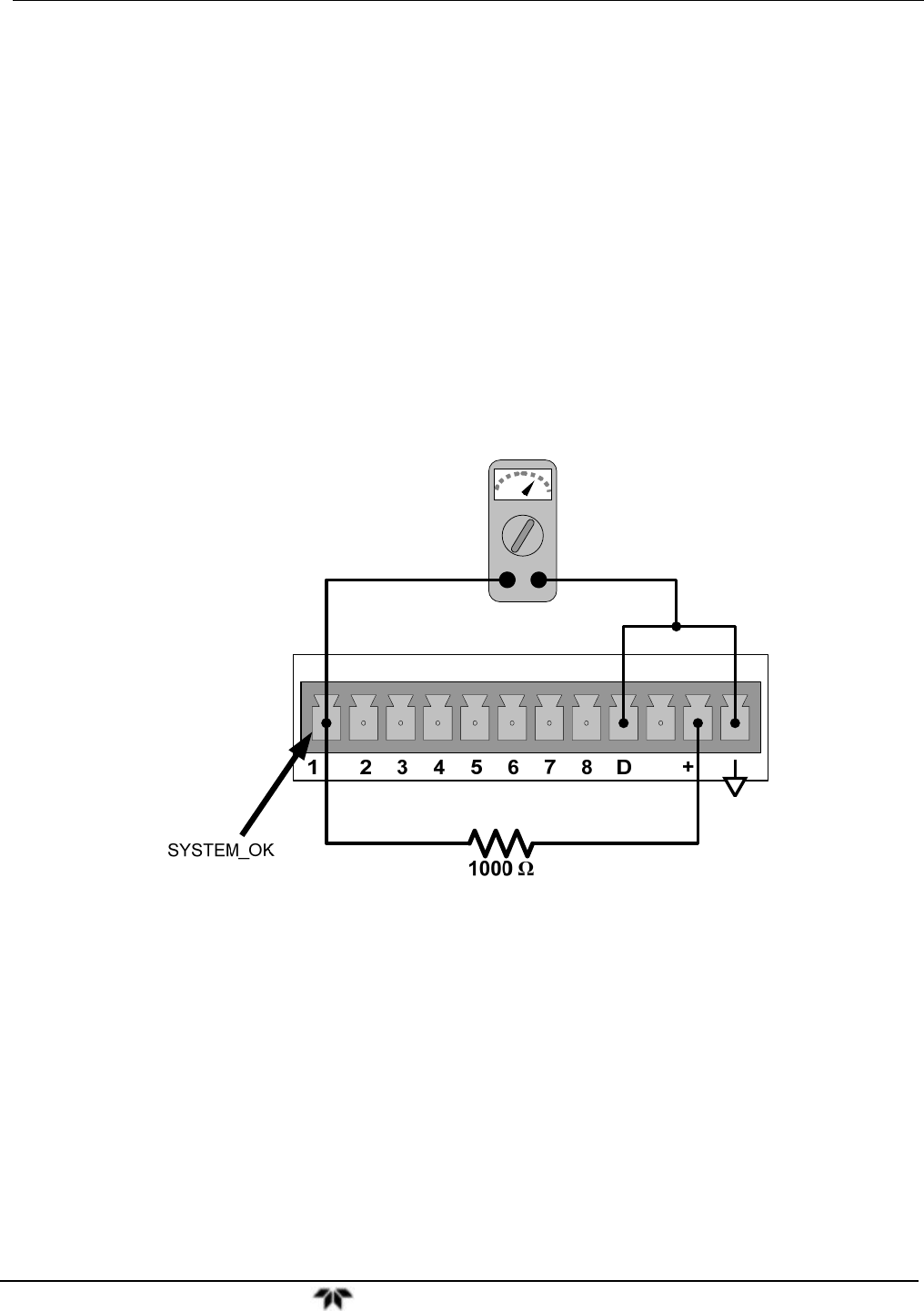
Figure 12-5: Typical Set Up of Status Output Test
To test the status output electronics:
1. Connect a jumper between the “D" pin and the “” pin on the status output
connector.
2. Connect a 1000 ohm resistor between the “+” pin and the pin for the status output
that is being tested.
3. Connect a voltmeter between the “” pin and the pin of the output being tested.
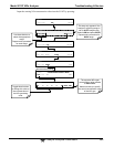
4. Under the DIAG Signal I/O menu (see Section 12.1.3), scroll through the inputs
and outputs until you get to the output in question.