


Model 9110T NOx Analyzer Troubleshooting & Service
Teledyne Analytical Instruments 303
1. Turn off the instrument power, and reconnect the PMT, and then reassemble the sensor.
If any faults are found in the test, you must obtain a new HVPS as there are no user
serviceable parts inside the supply.
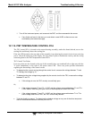
12.7.14. PMT TEMPERATURE CONTROL PCA
The TEC control PCA is located on the sensor housing assembly, under the slanted shroud, next to the
cooling fins and directly above the cooling fan.
If the red LED located on the top edge of this assembly is not glowing the control circuit is not receiving
power. Check the analyzers power supply, the relay board’s power distribution circuitry and the wiring
connecting them to the PMT temperature control PCA.
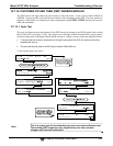
TEC Control Test Points
Four test points are also located at the top of this assembly they are numbered left to right start with the
T1 point immediately to the right of the power status LED. These test points provide information
regarding the functioning of the control circuit.
To determine the current running through the control circuit, measure the voltage between T1 and
T2. Multiply that voltage by 10.
To determine the drive voltage being supplied by the control circuit to the TEC, measure the voltage
between T2 and T3.
If this voltage is zero, the TEC circuitry is most likely open.
Or,
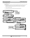
If the voltage between T2 and T3 = 0 VDC and the voltage measured between T1 and T2 =
0 VDC there is most likely an open circuit or failed op amp on control PCA itself.
If the voltage between T2 and T3 = 0 VDC and the voltage measured between T1 to T2 is
some voltage other than 0 VDC, the TEC is most likely shorted.
T4 is tied directly to ground. To determine the absolute voltage on any one of the other test points
make a measurement between that test point and T4.