


Model 9110TH NOx Analyzer Getting Started
Teledyne Analytical Instruments 45
The analyzer is now ready to have a voltage-sensing, recording device attached to that output.
Calibrate the analog output as described in Section 5.9.3.2.
3.3.1.5. Connecting the Status Outputs
The status outputs report analyzer conditions via optically isolated NPN transistors, which sink up to 50
mA of DC current. These outputs can be used interface with devices that accept logic-level digital
inputs, such as Programmable Logic Controllers (PLCs). Each Status bit is an open collector output that
can withstand up to 40 VDC. All of the emitters of these transistors are tied together and available at pin
D.
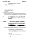
ATTENTION
COULD DAMAGE INSTRUMENT AND VOID WARRANTY
Most PLC’s have internal provisions for limiting the current that the input
will draw from an external device. When connecting to a unit that does
not have this feature, an external dropping resistor must be used to limit
the current through the transistor output to less than 50 mA. At 50 mA,
the transistor will drop approximately 1.2V from its collector to emitter.
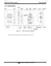
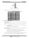
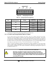
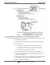
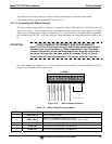
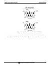
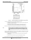
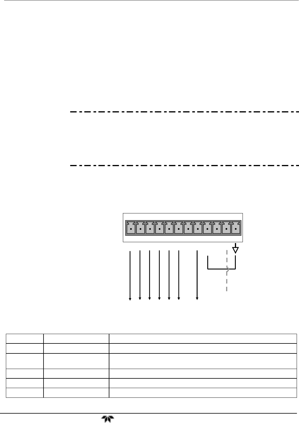
The status outputs are accessed via a 12-pin connector on the analyzer’s rear panel labeled STATUS
(Figure 3-4). Pin-outs for this connector are:
STATUS
1 2 3 4 5 6 7 8 D
+
SYSTEM OK
HIGH RANGE
CONC VALID
ZERO CAL
SPAN CAL
DIAG MODE
O
2
CAL
+5V to external device
Figure 3-10: Status Output Connector
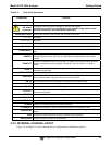
Table 3-6: Status Output Pin Assignments
OUTPUT # STATUS DEFINITION CONDITION
1
SYSTEM OK
On if no faults are present.
2
CONC VALID
On if O
3
concentration measurement is valid.
If the O
3
concentration measurement is invalid, this bit is OFF.
3
HIGH RANGE
On if unit is in high range of DUAL or AUTO Range Modes.
4
ZERO CAL
On whenever the instrument is in CALZ mode.
5
SPAN CAL
On whenever the instrument is in CALS mode.