


Model 9110T NOx Analyzer Troubleshooting & Service
Teledyne Analytical Instruments 289
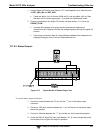
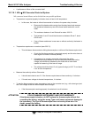
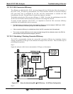
12.7.7. PRESSURE / FLOW SENSOR ASSEMBLY
The flow and pressure sensors of the 9110T are located on a PCA just behind the PMT sensor (see
Figure 3-5) can be checked with a Voltmeter.
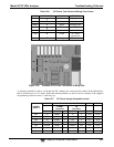
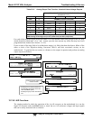
Figure 12-6: Pressure / Flow Sensor Assembly
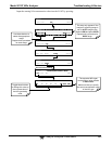
The following procedure assumes that the wiring is intact and that the motherboard and power supplies
are operating properly:
12.7.7.1. Basic PCA Operation Check:
Measure the voltage between TP2 and TP1 C1 it should be 10 VDC ± 0.25 VDC. If not then the
board is bad. Replace the PCA.
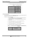
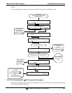
12.7.7.2. Sample Pressure Sensor Check:
1. Measure the pressure on the inlet side of S1 with an external pressure meter.
2. Measure the voltage across TP4 and TP1.
The expected value for this signal should be:
EXAMPLE: If the measured pressure is 20 Hg-in-A, the expected voltage level between TP4 and TP1
would be between 2870 mVDC and 3510 mVDC.