


Model 9110T NOx Analyzer Principles of Operation
Teledyne Analytical Instruments 345
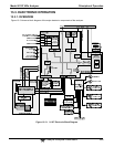
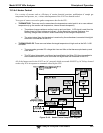
13.3.3.8. Power-Up Circuit
This circuit monitors the +5V power supply during start-up and sets the analog outputs, external digital
I/O ports, and I
2
C circuitry to specific values until the CPU boots and the instrument software can
establish control.
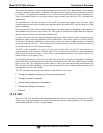
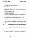
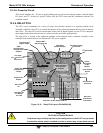
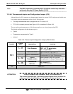
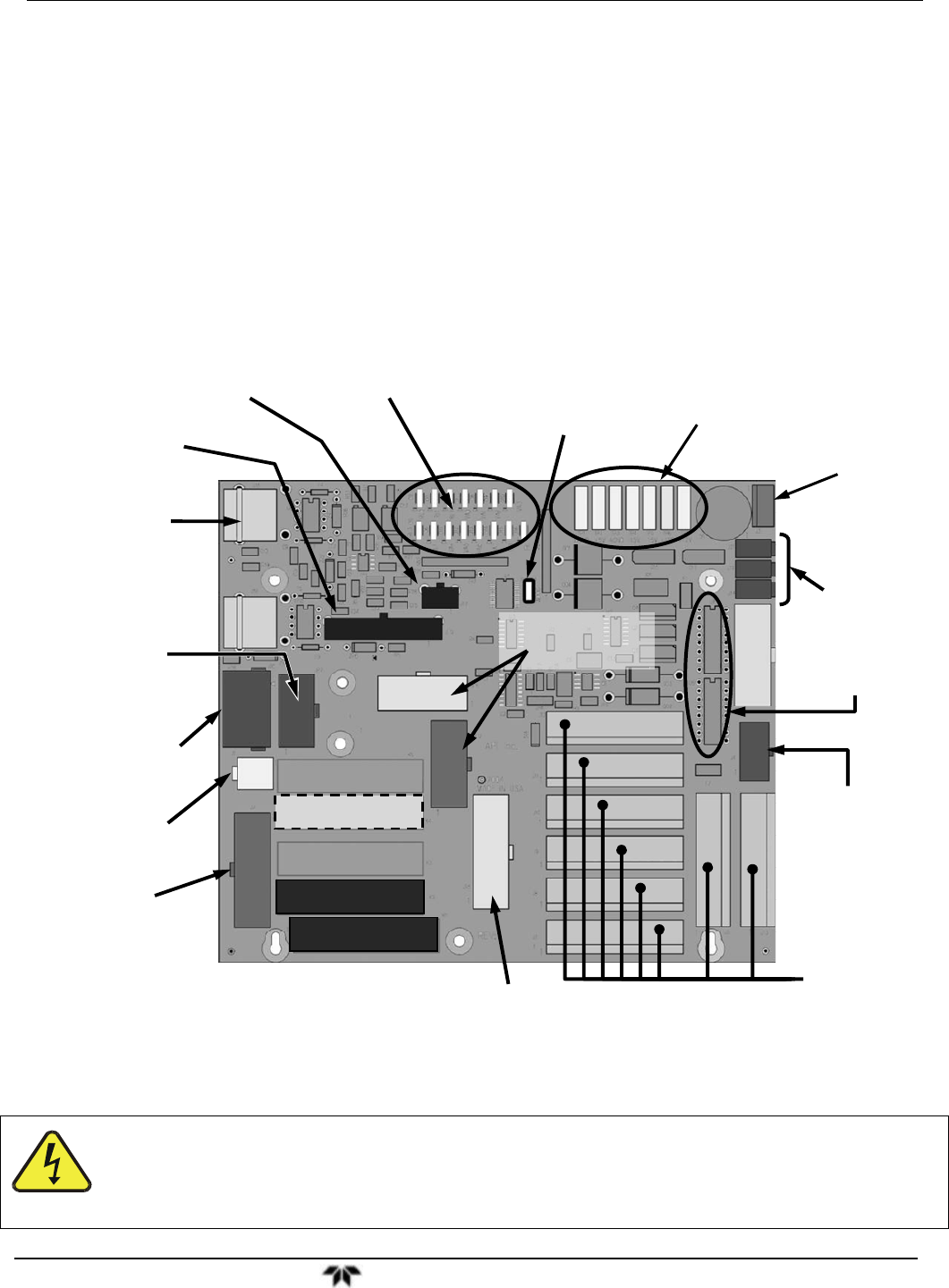
13.3.4. RELAY PCA
The CPU issues commands via a series of relays and switches located on a separate printed circuit
assembly, called the relay PCA, to control the function of key electromechanical devices such as heaters
and valves. The relay PCA receives instructions in the form of digital signals over the I
2
C bus, interprets
these digital instructions and activates its various switches and relays appropriately.
The relay PCA is located in the right-rear quadrant of the analyzer and is mounted vertically on the
backside of the same bracket as the instrument’s DC power supplies.
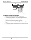
Power
Connection
for DC
Heaters
Status LED’s
(D2 through D16)
DC Power Supply
Test Points
Watchdog
Status LED (D1)
(JP5)
Thermocouple
Configuration
Jumpers
Thermocouple
Signal Output
I
2
C
Connector
V
alve Control
Drivers
Pump Power
Output
Pump AC
Configuration
Jumper
AC Power
IN
DC Power
Distribution
Connectors
V
alve Control
Connector
TC1 Input
NO
2
NO Converter
Temp Sensor
Connector for
AC Relays
K1 & K2
Connector for AC Relays K4 & K5
Heater AC Power
Configuration
Jumpers
JP2
JP6
J15
J16
R16
J17
J2
JP7
J18
TP1
TP2
TP3
TP4
TP5
TP6
TP7
J21
J19
J14
U5 U6
J4
J12
J11
J10
J9
J8
J7
J5
J13
J3
AC Relay K1
(Reaction Cell Heater)
AC Relay K2
(NO
2
NO Converter Heater)
AC Relay K4
(OPT Internal Span Gen Heater)
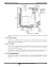
Figure 13-15: Relay PCA Layout (P/N 045230100)
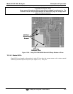
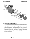
CAUTION
ELECTRICAL SHOCK HAZARD
Only those relays actually required by the configuration of the 9110T are populated.
A protective retainer plate is installed over the ac power relay to keep them securely