


Model 9110T NOx Analyzer Principles of Operation
Teledyne Analytical Instruments 348
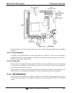
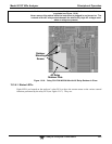
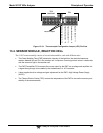
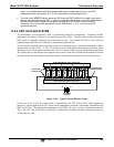
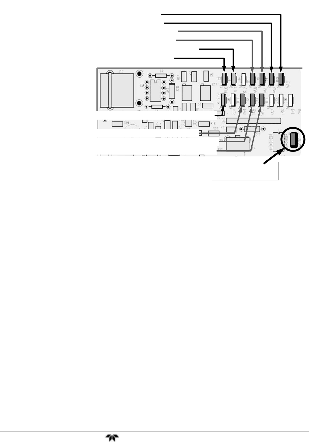
D7 (Green) – Optional Zero/Span Valve
D11 (Green) – Optional Dual Span Select Valve
D12 (Green) – Optional Pressurized Span Shutoff Valve
D3
(
Yellow
)
NO
2
NO Converter Heate
r
D5 (Yellow) – Optional Internal Span Gas Gen Heater
D8 (Green) – Optional Sample/Cal Valve
D1 (RED)
Watchdog Indicator
D2
(
Yellow
)
Reaction Cell Heater
D9
(
Green
)
–
AutoZero Valve
D10
(
Green
)
–
NO/NO
x
V
alve
D13 (Green) – Optional Pressurized Zero Shutoff Valve
Figure 13-17: Status LED Locations – Relay PCA
13.3.4.2. Watchdog Circuitry
The most important of the status LED’s on the relay board is the red I
2
C bus watch-dog LED. It is
controlled directly by the analyzer’s CPU over the I
2
C bus. Special circuitry on the relay PCA watches
the status of D1. Should this LED ever stay ON or OFF for 30 seconds, indicating that the CPU or I
2
C
bus has stopped functioning, this Watchdog Circuit automatically shuts all valves and turns off all
heaters.
13.3.4.3. Valve Control
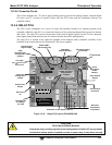
The relay board also hosts two valve driver chips, each of which can drive up four valves. The main
valve assembly in the 9110T is the NO/NO
X
- Auto-zero solenoid valve component mounted right in
front of the NO
2
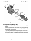
converter housing (see Figure 3-5).
These two valves are actuated with 12 V supplied from the relay board and under the control of the
CPU through the I
2
C bus.
Additional valve sets also controlled by the CPU via the I
2
C bus and the relay PCA can be included in
the 9110T (see Table 1-1 and Sections 3.3.2.3, 3.3.2.4, and 3.3.2.5 for descriptions of these valve sets).