


Model 9110T NOx Analyzer Troubleshooting & Service
Teledyne Analytical Instruments 288
5. Alternately, turn on and off the output noting the voltage on the voltmeter.
It should vary between 0 volts for ON and 5 volts for OFF.
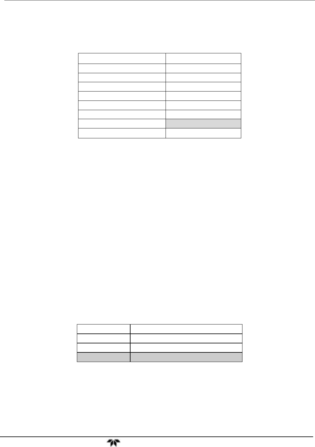
Table 12-10: Status Outputs Check
PIN (LEFT TO RIGHT) STATUS
1
ST_SYSTEM_OK
2
ST_CONC_VALID
3
ST_HIGH_RANGE
4
ST_ZERO_CAL
5
ST_SPAN_CAL
6
ST_DIAG_MODE
7
Not Used on 9110T
8
ST_O2_CAL
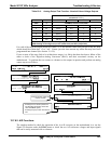
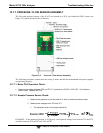
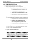
12.7.6.4. Control Inputs
The control input bits can be tested by applying a trigger voltage to an input and watching changes in the
status of the associated function under the SIGNAL I/O submenu:
EXAMPLE: to test the “A” control input:
1. Under the DIAG Signal I/O menu (see Section 12.1.3), scroll through the inputs
and outputs until you get to the output named EXT_ZERO_CAL.
2. Connect a jumper from the “+” pin on the appropriate connector to the “U” on the
same connector.
3. Connect a second jumper from the “” pin on the connector to the “A” pin.
4. The status of EXT_ZERO_CAL should change to read “ON”.
5. Connect a second jumper from the “” pin on the connector to the “B” pin.
6. The status of EXT_ZERO_CAL should change to read “ON”.
Table 12-11: 9110T Control Input Pin Assignments and Corresponding Signal I/O
Functions
INPUT CORRESPONDING I/O SIGNAL
A EXT_ZERO_CAL
B EXT_SPAN_CAL1
C, D, E& F NOT USED