


Model 9110T NOx Analyzer Calibration Procedures
Teledyne Analytical Instruments 194
This section describes how to judge the effectiveness of a recently performed calibration.
SECTION 9.7 – Gas Flow Calibration
This section describes how to adjust the gas flow calculations made by the CPU based on pressure and
flow sensor readings.
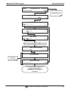
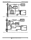
Note Throughout this Section are various diagrams showing pneumatic
connections between the 9110T and various other pieces of equipment
such as calibrators and zero air sources.
These diagrams are only intended to be schematic representations of
these connections and do not reflect actual physical locations of
equipment and fitting location or orientation.
Contact your regional EPA or other appropriate governing agency for
more detailed recommendations.
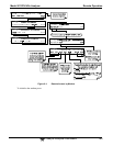
9.1. BEFORE CALIBRATION
The calibration procedures in this section assume that the range mode, analog range and units of measure
have already been selected for the analyzer. If this has not been done, please do so before continuing
(see Section 5.4.3 for instructions).
Note If any problems occur while performing the following calibration
procedures, refer to Section 12.1 for troubleshooting tips.
9.1.1. REQUIRED EQUIPMENT, SUPPLIES, AND EXPENDABLES
Calibration of the 9110T NO
x
Analyzer requires:
Zero-air source.
Span gas source.
Gas lines - all gas line materials should be stainless steel or Teflon-type (PTFE or FEP).
High-concentration NO gas transported over long distances may require stainless steel to
avoid oxidation of NO due to the possibility of O
2
diffusing into the tubing.
A recording device such as a strip-chart recorder and/or data logger (optional).
For electronic documentation, the internal data acquisition system (DAS) can be used.