


Model 9110T NOx Analyzer Principles of Operation
Teledyne Analytical Instruments 358
SENSOR MODULE
LOGIC DEVICES
(e.g. CPU, I
2
C bus,
MotherBoard, etc.)
RELAY PCA
ON / OFF
SWITCH
PS 2
(+12 VDC)
OPTIONAL
VALVES
(e.g. Sample/Cal,
Zero/Span, Shutoff,
etc.)
MODEL SPECIFIC
VALVES
(e.g. NO
X
– NO Valves,
Auto-zero valves, etc.)
Fans:
TEC and
Chassis
PUMP
(Internal Only)
AC HEATERS
NO2
NO
(Converter &
Reaction Cell)
Optional
AC HEATERS
( Internal Span
Generator Perm Tube
Heater)
PS 1
ANALOG
SENSORS
(e.g. Temp
Sensors, Flow
Sensors)
Pre-Amplifiers
& Amplifiers
Sensor Control
& I/O Logic
Solenoid
Drivers
KEY
AC POWER
DC POWER
AC
POWER IN
+5 VDC
±15 VDC
Configuration
Jumpers
Configuration
Jumpers
HVPS PMT
O
3
Generator
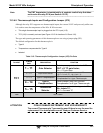
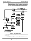
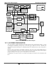
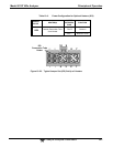
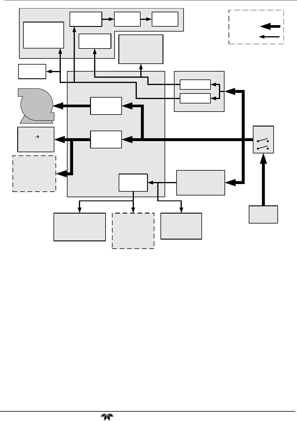
Figure 13-25: Power Distribution Block Diagram
13.7.1. AC POWER CONFIGURATION
The 9110T analyzer’s digital components will operate with any of the specified power regimes. As long
as instrument is connected to 100-120 VAC or 220-240 VAC at either 50 or 60 Hz,. Internally, the
status LEDs located on the Relay PCA, Motherboard and CPU should turn on as soon as the power is
supplied.
However, some of the analyzer’s non-digital components, such as the various internal pump options or
the AC powered heaters for the NO
2
NO converter the reaction cell and some of the 9110T’s must be
properly configured for the type of power being supplied to the instrument.
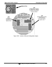
Configuration of the power circuits is set using several jumper sets located on the instruments relay
PCA.