


Model 9110T NOx Analyzer Troubleshooting & Service
Teledyne Analytical Instruments 308
12.8. SERVICE PROCEDURES
This section contains some procedures that may need to be performed when a major component of the
analyzer requires repair or replacement.
Note Maintenance procedures (e.g., replacement of regularly changed
expendables) are discussed in Section 11 (Instrument Maintenance) and
are not listed here).
Also, there may be more detailed service notes for some of the below
procedures. Contact Teledyne Customer Service Department.
WARNING – ELECTRICAL SHOCK HAZARD
Unless the procedure being performed requires the instrument be operating, turn it
off and disconnect power before opening the analyzer and removing, adjusting or
repairing any of its components or subsystems.
CAUTION – QUALIFIED TECHNICIAN
The operations outlined in this chapter are to be performed by qualified
maintenance personnel only.
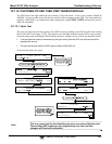
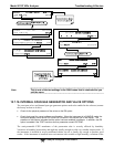
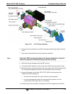
12.8.1. DISK-ON-MODULE REPLACEMENT PROCEDURE
Note Servicing of circuit components requires electrostatic discharge
protection, i.e. ESD grounding straps, mats and containers. Failure to use
ESD protection when working with electronic assemblies will void the
instrument warranty. Refer to Section 14 for more information on
preventing ESD damage.
Replacing the Disk-on-Module (DOM) will cause loss of all DAS data; it may also cause loss of some
instrument configuration parameters unless the replacement DOM carries the exact same firmware
version. Whenever changing the version of installed software, the memory must be reset. Failure to
ensure that memory is reset can cause the analyzer to malfunction, and invalidate measurements. After
the memory is reset, the A/D converter must be re-calibrated, and all information collected in Step 1
below must be re-entered before the instrument will function correctly. Also, zero and span calibration
should be performed.
1. Document all analyzer parameters that may have been changed, such as range,
auto-cal, analog output, serial port and other settings before replacing the DOM.
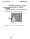
2. Turn off power to the instrument, fold down the rear panel by loosening the
mounting screws.
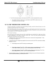
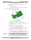
3. While looking at the electronic circuits from the back of the analyzer, locate the
Disk-on-Module in the right-most socket of the CPU board.
4. The DOM should carry a label with firmware revision, date and initials of the
programmer.