


Model 9110T NOx Analyzer Principles of Operation
Teledyne Analytical Instruments 344
For information on setting up the status outputs (see Section 3.3.1.4).
CONTROL INPUTS: By applying 5V DC power to these digital inputs from an external source such as
a PLC or Data logger zero point and span point calibrations can be remotely initiated. .
For information on setting up the status inputs (see Section 3.3.1.6).
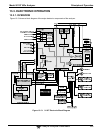
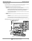
13.3.3.6. Internal Digital I/O
There are several internal digital control signals that are generated by the motherboard under CPU
control and used to control subsystems of the analyzer.
ELECTRICAL TEST CONTROL: When the CPU sets this control signal to high (ON) the electric
test feature (ETEST) is initiated (see Section 8.3).
The ETEST can be initiated by following the procedure in Section 12.7.12.2, or by setting the
SIGNAL I/O Function ELEC_TEST to ON.
OPTICAL TEST (OTEST) CONTROL: When the CPU sets this control signal to high (ON) the
optical test feature is initiated (see Section 8.3).
The OTEST can be initiated by following the procedure in 12.7.12.1, or by setting the SIGNAL I/O
Function OPTIC_TEST to ON.
PMT PREAMPLIFIER RANGE CONTROL: The CPU uses this control switch the instrument
between its LOW and HIGH physical ranges (see Section 5.4.1).
The instrument can be forced into its HIGH physical range setting the SIGNAL I/O function
PREAMP_RANGE_HI to ON.
O
3
GEN STATUS: The CPU uses this control signal to turn the O
3
generator ON/OFF by setting it to
HIGH/LOW respectively. The CPU turns OFF the O
3
generator if there is if there is no or low air flow
to it as measured by the O
3
flow sensor or if the instrument has been turned off for more than 30 minutes.
The O
3
generator can be manually turned ON/OFF by using the OZONE GENERATOR OVERIDE
feature (See Section 12.7.15.1) or by setting the SIGNAL I/O function O3GEN_STATUS to ON or
OFF.
Note Any I/O signals changed while in the signal I/O menu will remain in effect
ONLY until signal I/O menu is exited.
The analyzer regains control of these signals upon exit and returns them
to their normal value/setting.
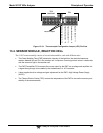
13.3.3.7. I
2
C Data Bus
I
2
C is a two-way, clocked, bi-directional digital serial I/O bus that is used widely in commercial and
consumer electronic systems. A transceiver on the Motherboard converts data and control signals from
the PC-104 bus to I
2
C format. The data is then fed to the relay board, optional analog input board and
valve driver board circuitry.