Model 9110TH NOx Analyzer Getting Started
Teledyne Analytical Instruments 47
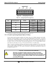
Digital Ground
The ground level from the analyzer’s internal DC Power Supplies (same as chassis
ground).
U
External Power
input
Input pin for +5 VDC required to activate pins A – F.
+
5 VDC output
Internally generated 5V DC power. To activate inputs A – F, place a jumper between
this pin and the “U” pin. The maximum amperage through this port is 300 mA
(combined with the analog output supply, if used).
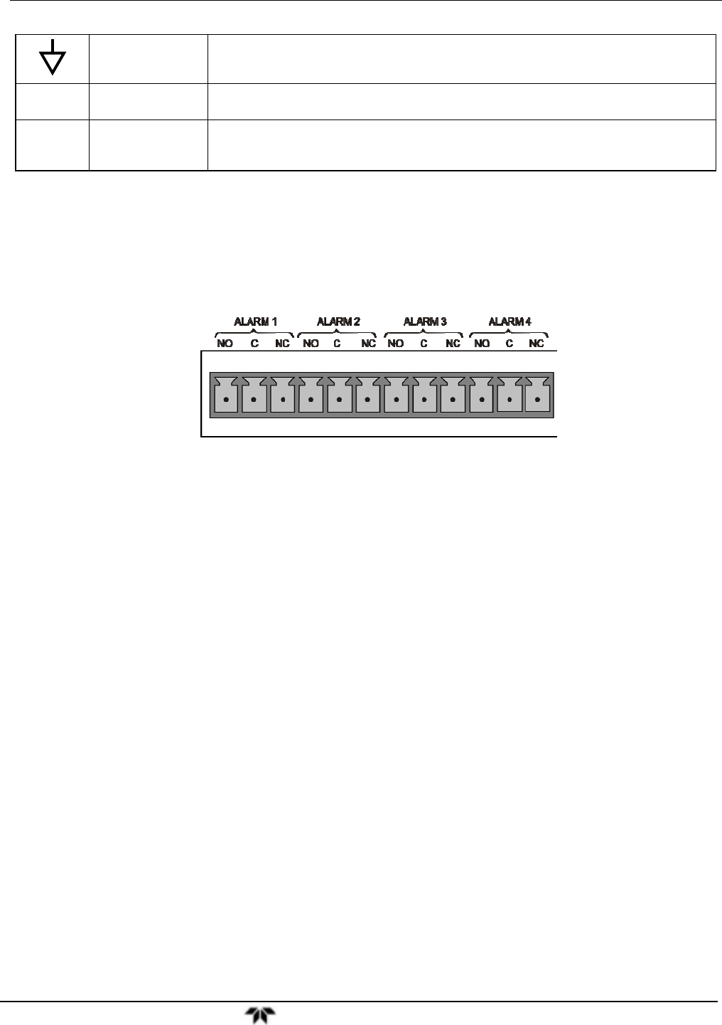
3.3.1.7. Concentration Alarm Relay (Option 61)
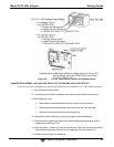
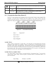
The TAI “E” series analyzers have an option for four (4) “dry contact” relays on the rear panel of the
instrument. This relay option is different from and in addition to the “Contact Closures” that come
standard on all TAPI instruments. The relays have 3 pins that have connections on the rear panel (refer
Figure 3-12). They are a Common (C), a Normally Open (NO), & a Normally Closed (NC) pin.
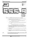
Figure 3-12: Concentration Alarm Relay
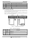
Alarm 1 “System OK 2”
Alarm 2 “Conc 1”
Alarm 3 “Conc 2”
Alarm 4 “Range Bit”
“ALARM 1” RELAY
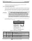
Alarm 1 which is “System OK 2” (system OK 1, is the status bit) is in the energized state when the
instrument is “OK” & there are no warnings. If there is a warning active or if the instrument is put into
the “DIAG” mode, Alarm 1 will change states. This alarm has “reverse logic” meaning that if you put a
meter across the Common & Normally Closed pins on the connector you will find that it is OPEN when
the instrument is OK. This is so that if the instrument should turn off or lose power, it will change states
& you can record this with a data logger or other recording device.
“ALARM 2” RELAY & “ALARM 3” RELAY
The “Alarm 2 Relay” on the rear panel, is associated with the “Concentration Alarm 1” set point in the
software & the “Alarm 3 Relay” on the rear panel is associated with the “Concentration Alarm 2” set
point in the software.
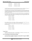
Alarm 2 Relay NO Alarm 1 = xxx PPM


