


Model 9110T NOx Analyzer EPA Protocol Calibration
Teledyne Analytical Instruments 233
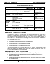
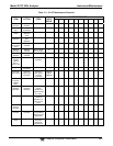
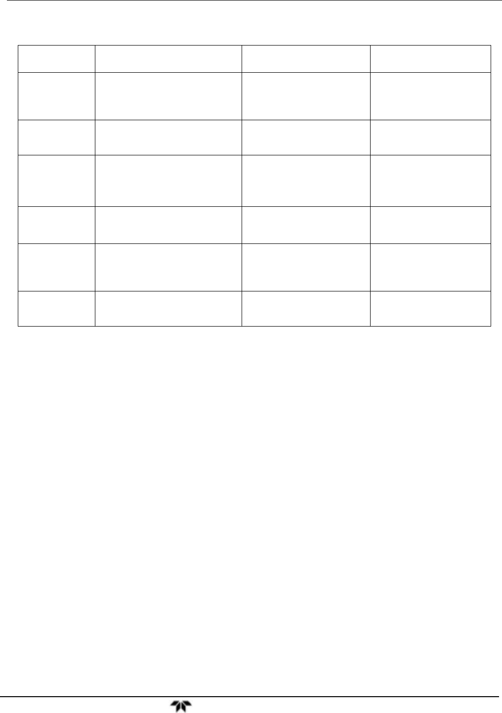
Table 10-3: Activity Matrix for Data Quality
Characteristic Acceptance Limits
Frequency and Method
of Measurement
Action if Requirements
are not Met
Shelter
temperature
Mean temperature between 22C
and 28C (72 and 82 F), daily
fluctuations not greater than 2C
Check thermograph chart
weekly for variations greater
than ± 2C (4F)
Mark strip chart for the
affected time period.
Repair or adjust
temperature control.
Sample
introduction
system
No moisture, foreign material,
leaks, obstructions; sample line
connected to manifold
Weekly visual inspection
Clean, repair, or replace as
needed.
Recorder
Adequate ink & paper
Legible ink traces
Correct chart speed and range
Correct time
Weekly visual inspection
Replenish ink and paper
supply.
Adjust time to agree with
clock; note on chart.
Analyzer
operational
settings
TEST measurements at nominal
values
9110T in SAMPLE mode
Weekly visual inspection Adjust or repair as needed.
Analyzer
operational
check
Zero and span within tolerance
limits as described in Section 12 of
the Q.A. Handbook
6
Level 1 zero/span every
2 weeks; Level 2 between
Level 1 checks at frequency
desired by user
Find source of error and
repair.
After corrective action, re-
calibrate analyzer.
Precision check Assess precision as described in
Sections 15&18 of the Q.A.
Handbook
6
Every 2 weeks, Subsection
3.4.3 (Ibid.)
Calc, report precision,
Section 12 of the Q.A.
Handbook
6
.
10.8.2. SHORT CALIBRATION CHECKS
A system of Level 1 and Level 2 zero/span checks (Table 10-2) is recommended. These checks must be
conducted in accordance with the specific guidance given in Section 12 of the Q.A. Handbook
6
. Level 1
zero and span checks must be conducted every two weeks. Level 2 checks should be conducted in
between the Level 1 checks at a frequency desired by the user. Span concentrations for both levels
should be between 70 and 90% of the measurement range.
Zero and span data are to be used to:
Provide data to allow analyzer adjustment for zero and span drift;
Provide a decision point on when to calibrate the analyzer;
Provide a decision point on invalidation of monitoring data.
These items are described in detail in Sections 15 & 18 of the Q.A. Handbook
6
. Refer to Section 11 of this
manual if the instrument is not within the allowed margins. We recommend using APICOM and the DAS
for analysis and documentation of zero/span check data.
10.8.3. ZERO/SPAN CHECK PROCEDURES
The Zero and span calibration can be checked in a variety of different ways. They include:
Manual zero/span checks can be done from the front panel touchscreen. The procedure is in
Section 9.2.2 of this manual.
Automatic zero/span checks can be performed every night. See Section 9.5 of this manual for setup
and operation procedures.