


Model 9110T NOx Analyzer Getting Started
Teledyne Analytical Instruments 46
6
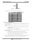
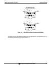
DIAG MODE
On whenever the instrument is in DIAGNOSTIC mode.
7-8
SPARE
D Emitter BUS The emitters of the transistors on pins 1 to 8 are bussed together.
SPARE
+ DC Power
+ 5 VDC, 300 mA source maximum
Digital Ground
The ground level from the analyzer’s internal DC power supplies. This
connection should be used as the ground return when +5VDC power is used.
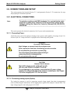
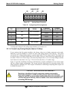
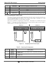
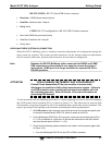
3.3.1.6. Connecting the Control Inputs
The analyzer is equipped with three digital control inputs that can be used to remotely activate the zero
and span calibration modes (see Section 9.1.2.4). Access to these inputs is provided via a 10-pin
connector labeled CONTROL IN on the analyzer’s rear panel.
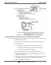
There are two methods for energizing the Control Inputs. The internal +5V available from the pin
labeled “+” is the most convenient method however, to ensure that these inputs are truly isolated; a
separate external 5 VDC power supply should be used.
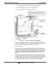
CONTROL IN
A B C D E F U
+
SPAN
ZERO
CONTROL IN
A B C D E F U
+
SPAN
ZERO
-
+
5 VDC Power
Supply
Local Power Connections
External Power Connections
Figure 3-11: Energizing the 9110T Control Inputs
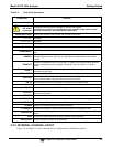
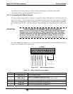
Table 3-7: Control Input Pin Assignments
Input #
Status
Definition
ON Condition
A
REMOTE
ZERO CAL
The Analyzer is placed in Zero Calibration mode. The mode field of the display will
read ZERO CAL R.
B
REMOTE
SPAN CAL
The Analyzer is placed in Lo Span Calibration mode. The mode field of the display will
read SPAN CAL R.
C, D, E
& F
Spare