


Model 9110T NOx Analyzer Troubleshooting & Service
Teledyne Analytical Instruments 310
These connect the inner drying tube to the outer purge tube and are delicate.
See Sections 13.3.1 and 11.3.2.
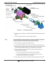
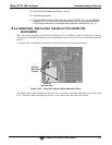
4. Note the orientation of the dryer on the bracket.
5. Cut the tie wraps that hold the dryer to the mounting bracket and take out the old
dryer.
If necessary, unscrew the two mounting screws on the bracket and take out the
entire assembly.
6. Attach the replacement dryer to the mounting bracket in the same orientation as the
old dryer.
7. Fix the dryer to the bracket using new tie wraps.
8. Cut off excess length of the wraps.
9. Put the assembly back into the chassis and tighten the mounting screws.
10. Re-attach the tubes to vacuum manifold, flow meter and/or NO/NOx valve using at
least two wrenches.
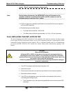
Take extra care not to twist the dryer’s white plastic fittings, as this will result in
large leaks that are difficult to trouble-shoot and fix.
11. Carry out a detailed leak check (see Section 11.3.12.2),
12. Close the analyzer.
13. Power up pump and analyzer and re-calibrate the instrument after it stabilizes.
12.8.4. PMT SENSOR HARDWARE CALIBRATION
The sensor module hardware calibration is used in the factory to adjust the slope and offset of the PMT
output and to optimize the signal output and HVPS.
If the instrument’s slope and offset values are outside of the acceptable range and all other more
obvious causes for this problem have been eliminated, the hardware calibration can be used to
adjust the sensor as has been done in the factory.
This procedure is also recommended after replacing the PMT or the preamplifier board.
To calibrate the PMT preamplifier PCA:
1. Perform a full zero point calibration using zero air (see Section 9).
2. Display the NOX STB test function on the front panel (Section 4.1.1).
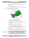
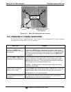
3. Locate the preamplifier board (see Figure 3-5).
4. Locate the following components on the preamplifier board (Figure 12-8):
HVPS coarse adjustment switch (Range 0-9, then A-F).
HVPS fine adjustment switch (Range 0-9, then A-F).